Understanding SM Driver Circuit, Building A Test Driver Voltage control Board

~Russ

Re: Understanding SM Driver Circuit, Building A Test Driver Voltage control Board
« Reply #350, on January 17th, 2017, 10:49 AM »Last edited on January 17th, 2017, 10:57 AM
Quote from gpssonar on January 17th, 2017, 03:53 AM
Matt, that photo is correct you just posted.
ok so here it is.


and attached is the equivalent.
and don's sketch. you can see there different.

in don's sketch
L2 and Sec,   there apposing 
L1 and Sec    there adding
L2 and L1      there apposing

In Ronnie's the wires to the cell's and Sec are switched. i left the arrows off for now because its confusing some one else check me.

what this means is that in Ronnie diagram
L2 and Sec,   there...
L1 and Sec    there...
L2 and L1      there...

I have looked at this for a long time, and now I'm getting confused lol

if you flip the coil, and the wires, you can get the same results. and i be leave thats what Ronnie did, so it comes out the same???


oh man...

by the way i see now that all the VIC coils are the same in the over all photos ( where all cards are layed out in one shot) , but the photos that Don has on the table when he was taking it apart are flipped!!!  everything is filliped! this will mess you up fast... and now its hard to tell whats what. 
basically its upside down!


Matt Watts

Re: Understanding SM Driver Circuit, Building A Test Driver Voltage control Board
« Reply #351, on January 17th, 2017, 10:59 AM »
Quote from ~Russ on January 17th, 2017, 10:49 AM
if you flip the coil, and the wires, you can get the same results.
Wind a little coil on a pencil and think about that.

If you flip only the coil (start/finish) and reconnect the wires in the same location nothing changes phase-wise.   But if you flip the wires, you toggle the phase.  If you want to change the phase, you have two choices:  Flip the wires or reverse the winding direction.  Start/finish doesn't matter to the phase.  It may matter if you need the high voltage outputs at the exterior of the coil instead of the interior though.


~Russ

Re: Understanding SM Driver Circuit, Building A Test Driver Voltage control Board
« Reply #354, on January 17th, 2017, 11:36 AM »
Quote from Matt Watts on January 17th, 2017, 11:03 AM
Problem with that photo is the phasing dots.  They are clearly wrong if all the windings are turned in the same rotation.
i see, well ok,

i connected my system up like in that photo. http://open-source-energy.org/?action=dlattach;topic=2820.0;attach=15004

I found it to be more interesting than what i got with don sketch drawing. but in the photo there i was not getting the chokes out of phase. only with don's sketch.

i would have to imagine that we want to cell to be " out of phase"  aka apposing voltage potential....

??

~Russ

Matt Watts

Re: Understanding SM Driver Circuit, Building A Test Driver Voltage control Board
« Reply #355, on January 17th, 2017, 12:05 PM »Last edited on January 17th, 2017, 12:14 PM
Quote from ~Russ on January 17th, 2017, 11:36 AM
i would have to imagine that we want to cell to be " out of phase"  aka apposing voltage potential....
At a glancing look I can see this to be true, but when you think about it a little deeper, we really want the two chokes in-phase.  Remember though, they can never be exactly in-phase because L2 has fewer turns.  So L2 will effectively finish its cycle time before that of L1 and the secondary.  If L2 finishes first, then it is already into the next cycle before L1 and secondary finishes.  This is the misalignment I'm talking about and I think this is where the polarization comes from, because what I see happening is each cycle actually resets by the VIC driver.  The VIC driver is synced to the feedback of the core which comes from the half of the core with the primary, the feedback coil and L2.  So what really happens is L2 sets the cycle time and L1 and the secondary never get a chance to completely finish a complete cycle.  So when L2 gets back to the zero volt mark, L1 and the secondary are still lagging behind with negative volts.  We can flip that by starting the signal low, then ending high--basically just move in the wave by 180 degrees.  In this case when L2 completes a cycle and is back at zero volts, L1 and the secondary are lagging behind with plus volts.  So to get optimal voltage from each cycle we would want L1 and the secondary lagging behind by 90 degrees, that would put it right at the peak voltage when the cycle is reset.

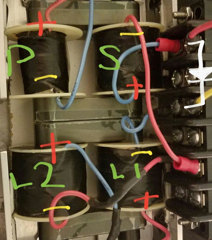
I think it is important to notice why L1 and the secondary are on one core half and L2 and the primary are on the other.  If they where on the same core with no gap, the VIC driver would attempt to force them all to follow the same cycle time, but with the loose coupling of the separate core halves and the gap, L1 and the secondary tend to oscillate at their own natural frequency which is lower than L2 and the driving signal of the primary.

I also think the diode between the secondary and L1 reduces much of the mutual inductance so that each coil tends to operate independently of the other, each at their own natural frequency.  Otherwise those two coils acting together as one big coil would have a frequency way lower than L2, probably less than half.  Ideally, each coil should oscillate at 75% of L2 to get maximum voltage polarization for each cycle of the VIC driver.


HMS-776

Re: Understanding SM Driver Circuit, Building A Test Driver Voltage control Board
« Reply #358, on January 17th, 2017, 09:57 PM »Last edited on January 17th, 2017, 10:13 PM
It gets even more confusing when you put the coils on two separate cores like many of us are doing.
I have my primary and secondary on one core and both chokes on the other....Not sure how else it will work since there is no coupling between two seperate cores?


Cycle

Re: Understanding SM Driver Circuit, Building A Test Driver Voltage control Board
« Reply #360, on January 17th, 2017, 10:26 PM »
Quote from Matt Watts on January 16th, 2017, 11:22 PM
This should be accurate if Don's sketch is what we base our work on.
Hi, Matt. Those graphics you posted triggered a long-buried memory about a PDF file I'd archived in my large compendium of research done by others, so I went digging.

The PDF is titled "Guidelines to Bucking Coils", by Chris Sykes at HyIQ.org. You might check it out for pointers.


HMS-776

Re: Understanding SM Driver Circuit, Building A Test Driver Voltage control Board
« Reply #361, on January 17th, 2017, 10:31 PM »Last edited on January 17th, 2017, 10:52 PM
Quote from Matt Watts on January 17th, 2017, 10:20 PM
I recall Ronnie talking about the two-core solution and that the cores need to physically touch each other at the right place.  So there should be some coupling.
We need to know for sure....If not were all shooting in the dark.


So...Now I am wanting to understand exactly what the diode does in the circuit and if it plays a role in the ground being moved between the secondary and L2 choke, or if that's simply due to the L2 choke opposing the secondary?

Dom

Re: Understanding SM Driver Circuit, Building A Test Driver Voltage control Board
« Reply #362, on January 18th, 2017, 12:07 AM »
Quote from Matt Watts on January 17th, 2017, 10:20 PM
I recall Ronnie talking about the two-core solution and that the cores need to physically touch each other at the right place.  So there should be some coupling.
Ronnie did say to place them side by side but not quite touching, however
In my set up i found best result having them positioned on top of each other
primary and L1 on the bottom and Sec and L2 on top in the same way stan has them visualy.
but Ron's set up will be different to mine so i can only assume that that i'm getting good output voltage wise
slight difference in coil will have different out come.
not sure if it matters at the moment but i'm only able to read 2000vac out the L1L2 no Cell.. 

HMS-776

Re: Understanding SM Driver Circuit, Building A Test Driver Voltage control Board
« Reply #363, on January 21st, 2017, 03:31 PM »Last edited on January 21st, 2017, 07:13 PM
Haven't been on in a few days.

I modified my vic box so the cores are touching each other...Primary and secondary coil are on one core, L1 & L2 are on another.

And yes you guys are right about the coils.

Here's what my coils look like now.


Dom, can you post a pic or drawing showing the layout of your coils?


Matt Watts

Re: Understanding SM Driver Circuit, Building A Test Driver Voltage control Board
« Reply #365, on January 21st, 2017, 07:58 PM »
Quote from HMS-776 on January 21st, 2017, 06:55 PM
One more thing...
Working on it HMS.  Russ wants original components for the voltage control, so I'm in the process of re-engineering it back and adding the ability to move some jumpers for direct signal generator input or onboard PLL.

I'll post the schematic when complete and test the bread-boarded version when my VIC is finished.  If it seems to do the job, I'll fab the boards for whoever wants one.

HMS-776

Re: Understanding SM Driver Circuit, Building A Test Driver Voltage control Board
« Reply #366, on January 21st, 2017, 09:31 PM »
Cool, Thanks for the update Matt.

Earlier today I tried setting up the primary and secondary on dual cores with the cores pushed together.

Result was not good, with 5v in the primary coil the secondary was only putting out 500mV open.

With both coils on the same core 3V on the primary puts out around 23V open.

So having the primary and secondary on the Chinese cores most of use are using results in terrible coupling and a huge voltage loss.

I wonder if there is a larger version with the same diameter legs that would fit all 4 coils on it?

Ronnie, are you using the same china cores? How are yours laid out?


Dom

Re: Understanding SM Driver Circuit, Building A Test Driver Voltage control Board
« Reply #369, on January 22nd, 2017, 04:35 AM »
Quote from HMS-776 on January 21st, 2017, 03:31 PM
Haven't been on in a few days.

I modified my vic box so the cores are touching each other...Primary and secondary coil are on one core, L1 & L2 are on another.

And yes you guys are right about the coils.

Here's what my coils look like now.


Dom, can you post a pic or drawing showing the layout of your coils?
Here are my coils i have removed them from my housing as the secondary coil is splitting and needs to be replaced.
The second pic is how i have wired it.


HMS-776

Re: Understanding SM Driver Circuit, Building A Test Driver Voltage control Board
« Reply #370, on January 22nd, 2017, 08:20 AM »
Nice setups guys,

Andy, we're you able to fit enough wire on there to match the resistances of Stans vic?
That looks great btw. I was thinking of doing something similar.

Dom,  have you checked to see if your coupling is any good?  Like I mentioned before when I try to put my cores together the coupling is terrible so I end up with a voltage loss.


Dom

Re: Understanding SM Driver Circuit, Building A Test Driver Voltage control Board
« Reply #373, on January 22nd, 2017, 02:46 PM »Last edited on January 22nd, 2017, 02:49 PM
Dom,  have you checked to see if your coupling is any good?  Like I mentioned before when I try to put my cores together the coupling is terrible so I end up with a voltage loss.

Not exactly... as I'm unsure as to how to check the actual coupling of the cores but I have tried several different ways of positioning and found the best results when placed as in my pic...

Brad the only thing I can see different in your setup is your coil position I'm sure you already know your primary and secondary are on same core,
Have the primary and L1 on one core and secondary and L2 on the other...
bellow 9vdc input I get 100 to one step up to A/C over 9vdc input I get approx 150 to 1, I found that with my pwm and gate set to minimum 2v in getting 230vac out as I increase the frequency  the output drops until I find the rite voltage in to match the frequency and same goes if I increase or alter the voltage input then again I find the rite frequency and voltage jumps up again. I get a spark ark at around 850vac across a spark plug capped to approx 1mm that's when the coils start crackling I only have the coils power supply frequency and gate band that's all, I couldn't see how Ronnie was getting spark plug to spark with transistors etc so there's more to learn there..