"Understanding How Stan Meyers Fuel Cell Works"

Matt Watts

Re: "Understanding How Stan Meyers Fuel Cell Works"
« Reply #975, on December 31st, 2016, 03:24 PM »
Quote from HMS-776 on December 31st, 2016, 11:06 AM
Also, are we sure gating is energized?
Ronnie's waveforms from before looked like they weren't, that could be my mistake though.
The patent and estate photos say the gating is inverted from what we all thought.  Ronnie confirmed that to me as well.

I'm not sure where he had his scope probes connected.  If they were in front of the driver, the driver definitely inverts the signal.  If he had the probes between the output of the TIP120 and ground, that signal is inverted from what the primary sees.

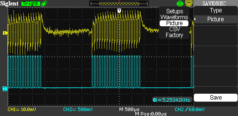
If you look at the PLL, pin-5 (INHIBIT) must be held low for the PLL to run.  When you bring pin-5 high, the PLL stops at a low state; that same signal goes to the driver which holds the primary energized.  Pin-5 is where the gating signal goes.
Quote from HMS-776 on December 31st, 2016, 11:06 AM
Another thing I'm not clear on is if I need to add a dc bias and if so how much. I've tried adding the bias before and still no resonance.
No DC bias to the primary.  Not on Stan's circuit.  The bias you are after is purely magnetic and that comes from the gating.

DC bias on the cell, that's another story.  That's your polarization from leakage current and the charge factor being unbalanced and out of phase.  I'm not that far yet, so I can only relate what I think needs to happen.
Quote from HMS-776 on December 31st, 2016, 11:06 AM
I'll try to figure out a way to make a pickup coil and do the ping test you mentioned, hopefully tomorrow morning. Thanks for the idea.
My thought was to use a current sense transformer.  A higher frequency one like the ICE CT07.  Take maybe ten turns of small wire around your core, go through the current sensor all ten times, then terminate the two wire ends with a 10 ohm resistor.

You should see some sort of signal on the current sense transformer when you pulse.  Don't let the voltage on the current sense transformer get too high or is will smoke the windings inside.  Use a shunt to keep it in range.

You may also want to move the ten turns of wire around to different places on the core to where you see the best signal or preferably the best ringing.
Quote from HMS-776 on December 31st, 2016, 11:06 AM
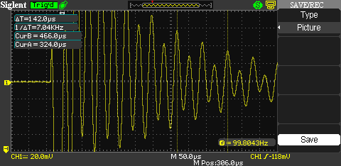
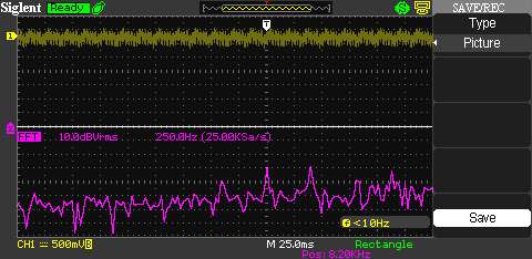
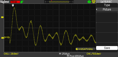
Update:I've been reading on the 'ring' test and came across something interesting...One person on another forum said if it takes 10 cycles for the voltage to drop to 1/e then your Q factor is 10....If that's true I should see about 350 oscillations?
Q indicates the damping factor--the higher the Q, the longer the oscillation runs before it damps out.  In reality, it never damps to zero.  It just gets really too small to measure.

The ping test is an electrical means to ring a bell and listen.  If you have any resonance at all, your cell, coils and core will ring at some natural frequency.  From what I understand from Ronnie, the higher the voltage, the higher the Q, which is why you need to start your tuning at low voltage so you can find resonance while the Q is rather flat.  As you increase your voltage, the Q goes up, gets sharper and it gets tougher and tougher to zero in on the exact frequency.  This is why Ronnie has stated several times, never, ever make frequency adjustments when running at full power.  The Q is way too sharp and just a few Hertz will knock it out of tune, then things smoke.  With that in mind, you can see why Stan's circuits have a PLL to constantly listen to the ringing and maintain phase alignment.  A PLL is the only thing fast and precise enough to make the needed adjustments when running flat out.

HMS-776

Re: "Understanding How Stan Meyers Fuel Cell Works"
« Reply #976, on December 31st, 2016, 04:57 PM »Last edited on December 31st, 2016, 07:39 PM
So, I used my current pickup coil placed on the lead between the secondary coil and L1 choke. I found peaks at 28kHz and 14kHz.
I tried pulses, bursts, and square waves at varying frequencies and continued to see the 28 and 14kHz peaks...What's cool is when you zoom in you see frequencies over 11MHz....and I'm sure they go into the GHz range from my own research a while back.

I also tried placing my probe directly on the insulated wire to be sure my current pickup coil was not effecting the peaks, it wasn't.
Here's a few shots.


Matt Watts

Re: "Understanding How Stan Meyers Fuel Cell Works"
« Reply #977, on December 31st, 2016, 05:19 PM »Last edited on December 31st, 2016, 05:25 PM
Cool stuff HMS.

Your scope appears to be a lot like mine.  Try a FFT run and see if that shows the peak frequencies.  Not nearly as good as a true spectrum analyzer, but you appear to be getting good signal so it should still show us what we need to know.


Something else worth investigating--biasing the core.  Here's my thought...

Forward magnetize the core with 12 volts, just for a second, then ping ASAP as you did.  Next, reverse magnetize the core and try pinging it again.  I'm very curious if the response changes at all.  If it does, then we are getting pretty certain as to what high-state gating is actually doing.


Gunther Rattay

Re: "Understanding How Stan Meyers Fuel Cell Works"
« Reply #979, on January 1st, 2017, 08:46 AM »Last edited on January 1st, 2017, 11:11 AM
Quote from HMS-776 on December 31st, 2016, 10:32 AM
Well, It looks like I still have more problems to solve. I think the differences in choke capacitances Cd and the capacitance to the case (I'll call it Cc) are making finding resonance difficult if not impossible.

This morning I used the sweep function on my signal generator to sweep from 8kHz to 10kHz over a period of about 33 minutes (1Hz/sec).
No resonance found. The work continues.

Here you can see the signals...The yellow shows the primary coil current via a current probe I made. The blue is the signal to the base of the TIP!20.

I also need to say that calculating resonance between the L1 choke and the cell gives me a frequency of 10,735Hz.
I measured the L1 capacitances and simulated the equivalent circuit, then found resonance had dropped to 8640Hz.
kudos to you for being the first within 6 years to show current signals of a vic.

now everyone should start thinking about the question why there is high frequency ripple in between low frequeny pulsing ...

HMS-776

Re: "Understanding How Stan Meyers Fuel Cell Works"
« Reply #980, on January 1st, 2017, 09:57 AM »
Thanks for the compliments Gunther. From what I can see there are a lot of harmonics in my VIC circuit, They go beyond frequencies my scope can pickup. The source of those HF ripples during the gating time is a question I wish I could answer. What do you think?


I tried doing an FFT today and I'm getting mixed results...I am seeing some peaks at 8.3kHz but they change often.
The FFT has me worried as it's not showing any clear signs of a center frequency...it looks like a lot of harmonics at similar amplitudes...
I have to admit FFT is new to me so I don't feel like I know what I'm doing here.
What kind of signals and frequencies should I be putting into the primary coil?


Gunther Rattay

Re: "Understanding How Stan Meyers Fuel Cell Works"
« Reply #981, on January 1st, 2017, 11:08 AM »Last edited on January 1st, 2017, 11:10 AM
Quote from HMS-776 on January 1st, 2017, 09:57 AM
Thanks for the compliments Gunther. From what I can see there are a lot of harmonics in my VIC circuit, They go beyond frequencies my scope can pickup. The source of those HF ripples during the gating time is a question I wish I could answer. What do you think?
maybe it´s antenna voltage/current with transformer coils working as LC-filters damping some airborne frequencies while others stay uninfluenced constant.

switch off pulsing and observe if signal stays constant or amplitude gets lower over time.

HMS-776

Re: "Understanding How Stan Meyers Fuel Cell Works"
« Reply #982, on January 1st, 2017, 11:29 AM »Last edited on January 1st, 2017, 09:12 PM
Some of it drops when the circuit is turned off....Some of it is noise getting picked up liked you mentioned because it doesn't go away even when the probe is disconnected.  The amplitudes are extremely small.

~Russ

Re: "Understanding How Stan Meyers Fuel Cell Works"
« Reply #983, on January 2nd, 2017, 12:12 AM »
Well even with a cemi pro wonder three things just arnt East to get exact. But that ok. It still turned out well.

One half done.  I have about 5 sets of thses coils with diffrent wire on them. So this wire i have here seems like it will handle the HV stress well.

I also took extra steps to place some ptfe linners that go in the bobbin edges.

I added extra windings so I could take some off. 3200 on the sec and 650 on the pri.

It's about 80ohms for the 3200 and 11.3ohms on the pri.

More mesurements later.

I do not know how I had all the patience to wind all the coils I have laying around.

~Russ

Matt Watts

Re: "Understanding How Stan Meyers Fuel Cell Works"
« Reply #984, on January 2nd, 2017, 06:29 AM »
I can hear Stan saying, "The only way this technology will come out is if the good people of the world make it happen."

Beautiful Russ!

It's going to happen.

HMS-776

Re: "Understanding How Stan Meyers Fuel Cell Works"
« Reply #985, on January 2nd, 2017, 08:59 AM »
Nice work Russ,

I'm still trying to figure out what's going on with my circuit...There is no clear sign of resonance that I can see. The problem is, I wonder, if the circuit has to be in full operation in order for resonance to appear?

This morning I connected a 390pF cap to my VIC to see if it was the cell that was causing my issues or the coils (I'm thinking it's the coils).
I performed the ring test again and see the same, harmonics and a possible resonant freq but it's hard to tell. Even on my FFT there are no clearly defined peaks, the peaks change continuously. I think we are starting to see what it is that makes this device so hard to replicate.

Anyways, my next test will be to remove the coils from their AL box and try the ring and FFT tests in the open....I might be able to get to that later today.

Here's a quick shot of the ring test I performed with a 390pF cap in place of the 180pF WFC.


~Russ

Re: "Understanding How Stan Meyers Fuel Cell Works"
« Reply #986, on January 2nd, 2017, 06:34 PM »
that's quite intresing brad.

I had know prob finding resonance. When I was doing this 2 years ago.

I'm getting closer. Will be able to help you. 

Even with the 2 core I was able to find resonance. What max voltage  peek have you seen?

~Russ

~Russ

Re: "Understanding How Stan Meyers Fuel Cell Works"
« Reply #987, on January 2nd, 2017, 06:35 PM »
This one is not bad at all. Tuning it all in. Resistance is really close to the same. But slightly off due to the other coil not wraping that well.

~Russ

HMS-776

Re: "Understanding How Stan Meyers Fuel Cell Works"
« Reply #988, on January 2nd, 2017, 08:52 PM »Last edited on January 2nd, 2017, 08:55 PM
Well, I finally found resonance, too bad it was with a 390pF cap and not the WFC.
It's easy to see on the FFT when using a regular capacitor in place of the WFC. Of course after I did this test I tried the WFC again and couldn't find resonance anywhere.
I know for sure that you can't use the Bandwidth formula for the VIC, If so I would have hit resonance a long time ago.
Here's a pic of what resonance is supposed to look like on an FFT.

Russ, I haven't seen anything close to resonance yet. I know I'm close but somewhere I am missing something or have a problem to correct.
Who knows when I will actually see it work? Hopefully soon

Matt Watts

Re: "Understanding How Stan Meyers Fuel Cell Works"
« Reply #989, on January 2nd, 2017, 09:58 PM »Last edited on January 2nd, 2017, 10:06 PM
Brad, do have the asymmetry in the L1 L2 ?   Meaning the L2 has fewer turns?

If so, how much of a difference in turns?

If you want to, there are quite a few liquids you might consider pouring into your cell to see if the capacitance becomes anywhere near the 390pF capacitor you are testing with.
http://www.engineeringtoolbox.com/liquid-dielectric-constants-d_1263.html

Are you certain your cell doesn't have a loose connection or possibly a short?   There's got to be a good reason why a real capacitor works and your cell does not.

~Russ

Re: "Understanding How Stan Meyers Fuel Cell Works"
« Reply #990, on January 2nd, 2017, 10:20 PM »
Oh man. Well that one is really good and L1 and L2 are all most identical.  Sec is ever so slightly different. So I may re wrap the sec. But good thing is that I think no got the coil winder tuned in. At least for this bobbin and wire.

Funny to think I printed these bobbins over 3 years ago.

Taking mesurments again.

Seems impedance with no core and 100Hz is spot on 100 ohms.

More when I get it.
~Russ


HMS-776

Re: "Understanding How Stan Meyers Fuel Cell Works"
« Reply #992, on January 2nd, 2017, 10:54 PM »Last edited on January 2nd, 2017, 10:56 PM
Matt,

I measured my coils again tonight and realized the secondary coils inductance is about 300mH (20%) too high. I knew that before but at the time I didn't think the secondary coil inductance would be a problem...the more I study Stan's tech the more I realize he did everything for a reason.

I checked my cell connections tonight and they are all good. I am getting the signals to the cell. More to come.


Haxar, the same thing happened to me. Then I tried glueing the core back together but it just didn't work. After that I went to a different core type. Those thin C cores are too brittle to mess with,  especially if the bobbins fit tight on them.

~Russ

Re: "Understanding How Stan Meyers Fuel Cell Works"
« Reply #993, on January 2nd, 2017, 11:30 PM »Last edited on January 2nd, 2017, 11:36 PM
very delicate hands here.. always have clearance here. i use the Steel ones i have first to get the fit right...  thanks for the heads up tho.

Brad, you still have one good core right?

here are the measurements on air core. i did not see the need for C measurements, ( i don't like the way that meter reads them any how)

This is fresh off the winder no adjustments yet.

Ronnie, what should i adjust from hear using your understanding of tuning. ? ( with theses measurements and no core)
everything is over the 3000,3000,3000,600 because from my last coils the resistance was to low, so i have plenty extra to match stuff by removing turns.  ill play dumb, teach me good sir.

hope your mom is getting better,

~Russ


HMS-776

Re: "Understanding How Stan Meyers Fuel Cell Works"
« Reply #996, on January 3rd, 2017, 10:03 AM »
Russ, the only way I could find resonance with the 390pF cap was when I removed the diode.

Resonance occurred between the secondary coil and cap....So today I'll be adjusting my secondary coil inductance.

When you hit resonance before did you have the diode installed?  Was your vic similar to Stan's measured values?


HMS-776

Re: "Understanding How Stan Meyers Fuel Cell Works"
« Reply #998, on January 3rd, 2017, 10:53 AM »
Btw everyone, what do you recommend and what are you using for an LCR meter?

I have a small one I bought on eBay a few years ago that works ok but doesn't have a case. I also have a mastech that worked fine a while but hasn't given me good measurements lately. Both were from China so I don't think they're very accurate.

Between the two I was getting completely different readings. So I took my coils and measured them on a Sencore LC103 and got better readings that were different from my meters at home.

Now I'm wondering if I should invest in a better LCR meter?