"Understanding How Stan Meyers Fuel Cell Works"

HMS-776

Re: "Understanding How Stan Meyers Fuel Cell Works"
« Reply #951, on December 22nd, 2016, 05:48 PM »Last edited on December 22nd, 2016, 06:05 PM
Russ your right about the AL value. It is meant to be low and is part of the design.

Getting the VIC working with a high AL core is probably not possible. I tried it years ago and found out when gapping the core that the inductance loss is exponentially related to the gap size, making it nearly impossible to tune. The tiniest gap would result in huge inductance changes and then any vibration would make it even worse.

If we can't find ferrite that will work Powdered Iron might be a choice, but we'd need to look further into it.

On a side note-What is everyone here using for the frequency generators?
I have a Chinese 2 channel unit that is OK but I'm not sure if it's tolerances are good enough as I can't find resonance with it.
I've been looking at the Siglent 1025 but read that the Siglent 1000 series have problems with low frequency square waves twitching?

HHO-Dan

Re: "Understanding How Stan Meyers Fuel Cell Works"
« Reply #952, on December 23rd, 2016, 01:31 AM »
I using a very old BK precision (4040) 20MHZ Analog Frequency Gen
Not really precision but it will go down to 2 Hz and will make a gated pulse train and drive a large Mosfet
Bought in 1998 when I first started testing the SM circuit.
I did go inside of it to tune the Gate to make it go faster....Might need to change it back.

nav

Re: "Understanding How Stan Meyers Fuel Cell Works"
« Reply #953, on December 23rd, 2016, 04:14 AM »
It's all gotten over complicated again. Remember some basic facts: Stan says L1 and L2 oppose the flow of current in the VIC, the only way you can do that is when L1 and L2 try to collapse their respective magnetic fields, both fields oppose each other so that the current of L1 and L2 are in opposition. Voltage is 90 degrees out of phase to the opposed fields because the opposed fields are 180 degrees. The voltage is escaping not linear down the wire but across the coils from winding to winding. Consider the imaginary below experiment. D1 and D2 cannot stop L1 and L2 from charging during pulse on time but they stop current from discharging into the resistance at R1 during pulse off time. If the voltage in L1 and L2 leads the current by 90 degrees during pulse off then there will be an applied voltage at C1 but only @ the self resonance of L1 and L2. C1 therefore must be in accordance with the self resonance. The voltage on C1 is NOT LINEAR it is SPATIAL.
Configure your chokes so that they replicate the diodes and you have current in opposition. Imagine that the entire VIC and the cell is ONE piece of equipment rather than many and that L1 and L2 are large capacitors but the current is blocked and the blocked current acts as a carrier wave for the voltage, but instead of the voltage trying to travel down the blocked path to create Q1 on a capacitor plate it travels 90 degrees to the blockage or perpendicular to the blockage. The easy way to understand this is to imagine 100 water pipes side by side joined by u bends at their ends and the water cannot move in the pipes because of the blockage, there is huge pressure inside the pipes. The voltage (pressure) escapes by jumping from pipe to pipe sideways but it does not burst the pipe, it stretches the pipe sideways and places a force on the next pipe so that you get a shock wave that stretches all the pipes sideways and when that shockwave hits the capacitor plate it places the same pressure on the plate and becomes Q1, Q2 is then created by Q1 creating the opposite shock wave on the other capacitor plate. None of the water pipes ever burst and the pressure remains high because the pipe is always blocked. The shock wave is not linear down the coil wires or the water pipes but it travels 90 degrees across them from pipe to pipe so it becomes Spatial.

HMS-776

Re: "Understanding How Stan Meyers Fuel Cell Works"
« Reply #954, on December 24th, 2016, 04:48 PM »
Not much going on.

I just bought a new signal generator (Siglent 1025) and am about to buy a Rigol 1054 oscilloscope. Should be a big step up from the cheap Feeltech signal generator I'm using now.

Merry Christmas and Happy New Year everyone!


andy

Re: "Understanding How Stan Meyers Fuel Cell Works"
« Reply #956, on December 25th, 2016, 11:05 PM »Last edited on December 26th, 2016, 03:05 AM
Matt and Ronnie
If the signal from PLL output "G" doing directly to "G" cell driver , then in the gate time TIP120 is turn-on and primary is also turn-on.
Please consider how the VIC behave in that case --- maybe half core of primary and L2 is saturated or became like electro-magnet in the gate time? How this influence the secondary and L1 and water cap interaction in the gate time?
thank for your attention.
andy


andy

Re: "Understanding How Stan Meyers Fuel Cell Works"
« Reply #958, on December 26th, 2016, 08:21 PM »
In the gate time when primary is turn-on , this cause that the core of primary became like magnet, The current that  flow thru water gap enter to L2 choke and generate magnetic field that is interacting with magnetic field of the core ( primary is turn-on ) - this cause the choke of current flow - restriction  current.
Sorry for my english.
andy

andy

Re: "Understanding How Stan Meyers Fuel Cell Works"
« Reply #959, on December 26th, 2016, 08:49 PM »
Sorry that I dont wish you all in the first place Merry Christmas , but I give you the gift of understanding that appears in my head or heart - thanks to God.

~Russ

Re: "Understanding How Stan Meyers Fuel Cell Works"
« Reply #960, on December 27th, 2016, 08:36 AM »
Quote from mercury101 on December 26th, 2016, 10:22 AM
Lol yes you have a point
Indeed I did nothing but a merry Christmas.

with 5 kids we had PLENTY of new things that needed building lol
i had a blast and i hope everyone else did too.
Quote from andy on December 26th, 2016, 08:49 PM
I give you the gift of understanding that appears in my head or heart - thanks to God.
agreed, thanks for the thought!!!

we will get there :)

~Russ


HMS-776

Re: "Understanding How Stan Meyers Fuel Cell Works"
« Reply #962, on December 30th, 2016, 03:55 PM »
Well, I feel like I've tried just about everything and still cannot hit resonance.

Right now I'm putting 3V square waves to the primary coil.
The rise time of the pulses going to the TIP120 base is 330ns and the fall time is 1.2us
I have my drive circuit setup on a breadboard. It produces variable amplitude pulsing during the gate "off" time and also gives me an adjustable DC bias if I need it but right now I have the square waves going to 0V. Even when I add a 500mV bias still no resonance?

I have been using the frequency sweep on my signal generator. It sweeps 1Hz per second with a resolution of .01 seconds.
Cell is 175pF and L1 choke is 1.221H, calculated resonance is 10,870Hz.
I am scanning from 10.7khz to 10.9kHz in a period of 5 minutes....


haxar

Re: "Understanding How Stan Meyers Fuel Cell Works"
« Reply #964, on December 30th, 2016, 05:13 PM »
Quote from HMS-776 on December 30th, 2016, 03:55 PM
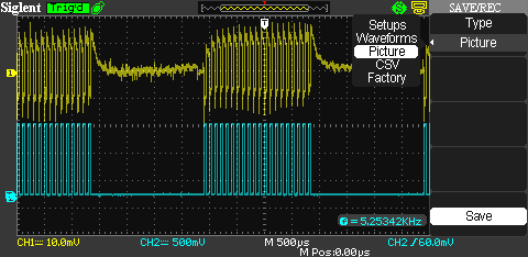
Well I feel like I've tried just about everything and still cannot hit resonance.

Cell is 175pF and L1 choke is 1.221H, calculated resonance is 10,870Hz.
Calculated is different from real world. The range for resonance is up to 25kHz. With frequency doubled, it takes you up to 50kHz.
Quote from HMS-776 on December 30th, 2016, 03:55 PM
I am scanning from 10.7khz to 10.9kHz in a period of 5 minutes....
Sweep up to 25kHz and see which frequency has a higher peak to peak RMS voltage.


HMS-776

Re: "Understanding How Stan Meyers Fuel Cell Works"
« Reply #966, on December 30th, 2016, 06:08 PM »
I have discovered the problem! I think!

I decided it would be best to isolate the circuit from the cell then the coils individually.

I applied a 390pF capacitance in place of the cell and still could not hit resonance.....So I then removed the L1 choke from the circuit and placed the 390pF cap in series with the L1 choke and a resistor.

 I hit resonance with the coil and cap in series but the voltage magnification only grew to 6X the applied voltage. I did the math and determined my voltage was only 1/100th of what it was supposed to be at resonance.

I then tested my freq gen to be sure it could supply the current at resonance to be sure it wasn't the culprit. It produces more than enough current.

Not only was the voltage and current low at resonance but the resonant frequency was about 1.3kHz below what it was supposed to be.

So, what can effect resonance so much that it reduces the coils q factor?
I believe it is the aluminum box I have my coils mounted in. See, the coils not only have a distributed capacitance between the windings, there is also a capacitance between the coil and the case.

Since the coils are nearly identical to Stan's in the number of turns and wire size I don't think it is the Cd that is causing the problem...It's the C between the coils and the case.

Unfortunately this is going to create a lot of work to fix. My coils are mounted very well in that box, so perhaps a sturdy plastic box is needed.

Matt Watts

Re: "Understanding How Stan Meyers Fuel Cell Works"
« Reply #967, on December 30th, 2016, 06:19 PM »Last edited on December 30th, 2016, 06:21 PM
Depending upon the magnetic configuration, a metal case around such a transformer can act just like a shorted turn.  I've seen a lot of people try to mount a power toroid transformer with a bolt through the middle connected top-n-bottom to a metal case.  It no worky that way.

I'm glad you may have found the problem, but it also looks like you got way ahead of yourself building a fancy enclosure before things were ready for prime time.

A small piece at a time, making sure everything is working as it is suppose to before moving on to the next step is the best approach.  And don't assume anything.  Make absolutely certain.

~Russ

Re: "Understanding How Stan Meyers Fuel Cell Works"
« Reply #968, on December 30th, 2016, 06:28 PM »
So the AL box lowers the resonant frequency by adding more capatance. Thats not a bad thing??? I don't think? 

Thanks for posting your findings. I'll be there soon!  ~Russ

Matt Watts

Re: "Understanding How Stan Meyers Fuel Cell Works"
« Reply #969, on December 30th, 2016, 06:29 PM »
Also, with any kind of resonant system, you should be able to apply the ping test.  Basically hit the circuit with the fastest, sharpest pulse you possibly can and watch for any ringing on the scope after the pulse.  Use your cursors on the scope and find the exact cycle time; this should give you the resonant fundamental frequency you can tune to.  From there you can find all the harmonics for quarter wave resonance and set your signal generator to match any particular one you want.


HMS-776

Re: "Understanding How Stan Meyers Fuel Cell Works"
« Reply #970, on December 30th, 2016, 06:33 PM »
Thanks Matt and Russ.

I just went and simulated the circuit and I think it could work....Just need to reduce the frequency and search around more.
The bandwidth of the circuit is so narrow that it makes it very hard to find....especially when your 1kHz past where you think you need to be.

I'll do more testing tomorrow morning at lower frequencies.

gpssonar

Re: "Understanding How Stan Meyers Fuel Cell Works"
« Reply #971, on December 30th, 2016, 06:34 PM »Last edited on December 30th, 2016, 07:41 PM
The alum case will increase the capacitance of the coils, it's just like putting a alum dome on top of a Tesla coil. It all has to be factored in. As I told brad if you lay your coils on a wood table and move them to a plastic table or any other material once you get them to work, It is enough to change things and stop it from working. So what every you put your coils on or in, expect it to change the capacitance of the coils. Its best to use a alum enclosure like Stan did on all of his VIC and factor the capacitance in.

HMS-776

Re: "Understanding How Stan Meyers Fuel Cell Works"
« Reply #972, on December 31st, 2016, 10:32 AM »Last edited on December 31st, 2016, 10:39 AM
Well, It looks like I still have more problems to solve. I think the differences in choke capacitances Cd and the capacitance to the case (I'll call it Cc) are making finding resonance difficult if not impossible.

This morning I used the sweep function on my signal generator to sweep from 8kHz to 10kHz over a period of about 33 minutes (1Hz/sec).
No resonance found. The work continues.

Here you can see the signals...The yellow shows the primary coil current via a current probe I made. The blue is the signal to the base of the TIP!20.

I also need to say that calculating resonance between the L1 choke and the cell gives me a frequency of 10,735Hz.
I measured the L1 capacitances and simulated the equivalent circuit, then found resonance had dropped to 8640Hz.

Matt Watts

Re: "Understanding How Stan Meyers Fuel Cell Works"
« Reply #973, on December 31st, 2016, 10:46 AM »
What is the blank time in between bursts?

If that's gating, you have it backwards.  Gating is energized not relaxed.  And you shouldn't need very much gating--just enough to set the core magnetization bias--goes back to what Russ and I were talking about with flux walking.  I would gate for maybe three pulse widths, then pulse normally for the next 97 pulses in a 100 pulse cycle, just for starters.

Are you testing with your cells dry?

Also, I'm really thinking you need a few wraps of wire for a pickup coil.  You need to see magnetic ringing which could be obscured from your primary injection signal.  I have no idea what kind of amplitudes will show up as you get close to the resonance point.

I'm not in any way a master of this technology, so try my suggestions as you see fit.

If you want to, please try a ping test with some sort of pickup coil/wraps.  I'd be very curious myself if you detect any sort of ringing and if this ringing can be analyzed to find the actual resonant frequency.

HMS-776

Re: "Understanding How Stan Meyers Fuel Cell Works"
« Reply #974, on December 31st, 2016, 11:06 AM »Last edited on December 31st, 2016, 02:57 PM
Matt, thanks for the input.

You reminded me that my gate frequency was incorrect. I calculated it using the L/R time constant of the primary coil like Ronnie explained earlierbit I calculated it incorrectly.

Also, are we sure gating is energized?
Ronnie's waveforms from before looked like they weren't, that could be my mistake though.

Another thing I'm not clear on is if I need to add a dc bias and if so how much. I've tried adding the bias before and still no resonance.

I'll try to figure out a way to make a pickup coil and do the ping test you mentioned, hopefully tomorrow morning. Thanks for the idea.

Update:I've been reading on the ring down test. If you count the number of cycles till the voltage goes to zero and multiply it by 4.53 you get the circuits q factor. So I should see about 70 pulses.