for God's sake Take a plastic water pipe
Ris
Re: "Understanding How Stan Meyers Fuel Cell Works"
« Reply #1050, on January 10th, 2017, 12:39 PM »
Thanks Russ, one thing,
Can you measure the capacitance of your coils and post them? Just curious to see if you'll get the same values.
I still think my coils should work, but tuning into resonance is more complex than just turning a knob.
I scanned 5-10kHz in 10Hz increments and saw no sign of resonance anywhere, yesterday?
If you think of the cell as a efficient capacitor then you can calculate the Q and bandwidth of the circuit, then finding resonance should be easy, if I remember right my VIC had a calculated bandwidth of 74Hz.
I think the water has to change in some way before resonance will show up, and that's the hard part?
So, in essence you could have the circuit at resonance and nothing will happen until the water does whatever it does before resonance appears.
I think I've probably hit and passed resonance multiple times but didn't notice because I didn't keep it on the frequency long enough?
There's got to be something more because finding resonance in a typical RLC circuit is easy.
Webmug, Brad, and Ronnie
I have been deeply thinking about SRF, & How it can be directly applied to the known "what to do's"
so the first thing i want to do is that, measure all the SRF and resistances and try to determine if there is something useful there.
Ronnie, do you have anything to say about this path?
Webmug, using the same device you used i will be checking for SRF. would you mined posting any information on your experience even more than you already did? i think it would be helpful. also i dont have the device name here with me and forgot to post it. if you can that be great, if not ill get mine when i get home.
Brad, what have you been thinking as of the SRF and tuning / math? can you go deeper in to your thought process?
thanks!! hope to get some more data soon on SRF of the coils i made.
~Russ
Oh and somthinh to add. I was only able to see the doubling on the L1 coil. This makes sentce according to what I know about where the dioed is placed.
Max voltages I was seeing was around 165vPk-Pk
Ris, let me know if you see anything that size.
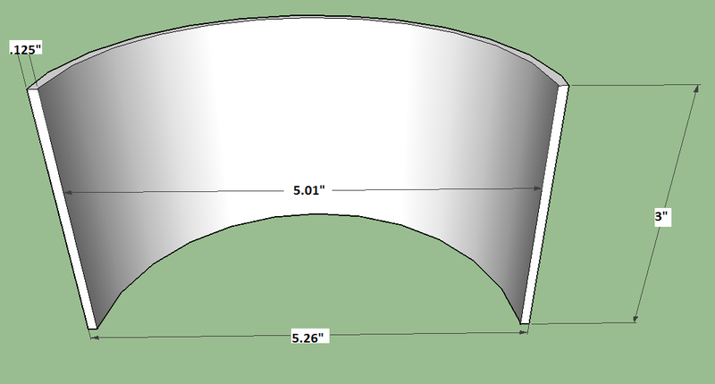
I looked locally and online and couldn't find anything that size, any smaller or bigger than those dimensions and it's not going to work.
Russ, here's a drawing of what I need x2, as you can see it's just a short pipe cut in half
Yellow is L2
Purple is L1
Blue is Sec
Green is primary