"Understanding How Stan Meyers Fuel Cell Works"

HMS-776

Re: "Understanding How Stan Meyers Fuel Cell Works"
« Reply #1125, on January 15th, 2017, 10:54 PM »
Haxar,

I think your right...but the question is, how do we get that extra current flow to the cell to begin the process?

I was working on my coils earlier today trying to find a way to eliminate the SRF then it dawned on me.

Their smaller coil capacitance is producing a much higher impedance than the cell, no wonder why my circuit acts as if the cell isn't even there. The coil impedances are so high that the circuit doesn't even see the cell.

I'm starting to wonder if we can start the process the dielectric value should drop as the bubbles form....If we can get the capacitance to drop low enough it's impedance will then dominate....Still need to think this through though...it's getting late.
haxar

Re: "Understanding How Stan Meyers Fuel Cell Works"
« Reply #1126, on January 15th, 2017, 11:04 PM »
Quote from HMS-776 on January 15th, 2017, 10:54 PM
I think your right...but the question is, how do we get that extra current flow to the cell to begin the process?
I think my findings are conclusive. Evidence can change at any time when reverse engineering. The evidence is mounting up.

The distinction I make: initial current flow to the self-resonant transformer, not to the cell.

Low impedance at the primary; high impedance at the secondary.

To your discretion: Thicker wire on the primary, or add another primary layer wired in parallel. It's total resistance/impedance must not drop below 4 ohms, otherwise you create a dead short at the primary. Have a look at a speaker's impedance, for example.

Matt Watts

Re: "Understanding How Stan Meyers Fuel Cell Works"
« Reply #1127, on January 16th, 2017, 12:43 AM »Last edited on January 16th, 2017, 12:55 AM
Quote from haxar on January 15th, 2017, 11:04 PM
The evidence is mounting up.
Indeed.

Duty cycle controls the self-resonance of the two chokes which are slightly out-of-tune with each other.  That's where we get polarization.  You can't charge anything without polarization.

Webmug

Re: "Understanding How Stan Meyers Fuel Cell Works"
« Reply #1128, on January 16th, 2017, 06:17 AM »Last edited on April 15th, 2017, 05:05 AM
edited: 01/30/2017
http://open-source-energy.org/?topic=1961.msg29371#msg29371 (Impedance matching thread)

Here is a lot of information of the VIC and WFC. This is a (resonance) AC analysis without the BLOCKING DIODE placed in the circuit.

If you noticed the WFC in the circuit Fig 7-8 Matt posted from the TB. You see the WFC with a Cp and a Re. Cp is the parasitic (parallel) capacitance and not the cell capacitance. Re is the resistance of the cells or ESR (Equivalent series resistance).

Now using a model in LTSpice, I match or balance the B+ and B- choke outputs using the properties of Cd, L of the coils. Two equal |Z| peaks at highest voltage and lowest current. Using a k (core coil coupling factor of 0.53 or 53% based on opposing coil mutual inductance).

The result is a charge curve.

So how does it behave in a real setup?

~webmug

HMS-776

Re: "Understanding How Stan Meyers Fuel Cell Works"
« Reply #1129, on January 16th, 2017, 09:08 AM »Last edited on January 16th, 2017, 09:30 AM
Matt & Webmug

You guys both make some great points in your last few posts. Do you have cells and VIC's you are testing?
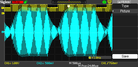
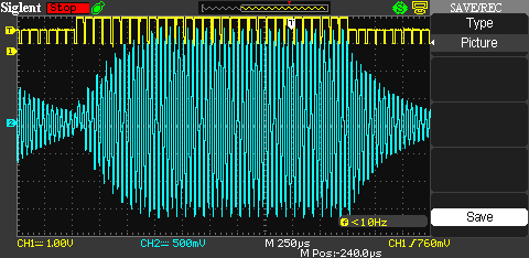
The reason I ask is because once you start testing you see similarities that simulations show just like you have shown. A few years back I simulated the VIC with the Cd of the chokes and got an amplitude modulated waveform with the classical waveforms you see in my scope shots here.

The problem I am seeing like I mentioned before is that the chokes are blocking the circuit from seeing the cell. I have adjusted the duty cycle in an effort to get more current to the cell but the chokes continue to block it all.

How do you suggest we get the right conditions set up?
Do you think the choke values need to match each cell in relation to the duty cycle?
Have you made any mathematical models to see that the chokes and duty cycle can maintain resonance over a broad frequency range?

This morning doing more testing I have achieved frequency doubling...But I am not sure if it's the right frequency doubling because I'm simply pulsing at a harmonic of the 24 kHz SRF of the coils. Here's a few shots of my latest work.


Also, I forgot to mention that if I'm at a particular frequency, as I adjust the duty cycle I see current rising and falling throughout the it's range as I adjust it from 1%-99%.

~Russ

Re: "Understanding How Stan Meyers Fuel Cell Works"
« Reply #1130, on January 16th, 2017, 10:08 AM »
Quote from HMS-776 on January 15th, 2017, 07:33 PM
Russ, my circuit does that same thing where it pops into a resonant frequency of some kind.....
ok good to know. its also important that i discovered that my L2 was in reverse in that video. 

i corrected it and the result are different.. video posted on the driver thread...

~Russ

~Russ

Re: "Understanding How Stan Meyers Fuel Cell Works"
« Reply #1131, on January 16th, 2017, 10:54 AM »
nice work web mug,
yeah Brad,

Keep thinking Matt and Hax,

let me through this in there. how do we remove damping? ANY damping and we lose our potential for resonance.

i think it has ALOT to do with SRF, if we can match the SRF and the VIC "system" resonant frequency, then if we start to look at the cell SRF... well you see where i'm going.

rule out all factors for damping... thats how we "let voltage take over"...

just thronging in my 2 cent.

~Russ

HMS-776

Re: "Understanding How Stan Meyers Fuel Cell Works"
« Reply #1132, on January 16th, 2017, 11:34 AM »
Russ, I looked at the damping factor of the coils a while back. They are all underdamped.

I thought they needed to be critically damped in order to get energy to the cell. After doing the math I realized it would take much more resistance than can be provided by the coils themselves.

I have also changed my coils orientation, phasing etc and every time I continue to get peaks in the 20-25kHz range.

~Russ

Re: "Understanding How Stan Meyers Fuel Cell Works"
« Reply #1133, on January 16th, 2017, 11:39 AM »
Brad, well i was thinking about trying to control for ALL factor's of where resonance could be damped.

any how i get your point.

any chance you can help us all understand what math your doing...
There is a bunch of things to look at here...
just an idea...

~Russ

HMS-776

Re: "Understanding How Stan Meyers Fuel Cell Works"
« Reply #1134, on January 16th, 2017, 12:51 PM »Last edited on January 16th, 2017, 01:31 PM
I'll look back in my notes to find the math....But if you look at the coils individually, find their SRF then calculate the capacitance, q factor etc you will see the coils are each far underdamped....Even Stan's coils were.

Looking at the L1 choke (C based on SRF)
L 1.262H.   C 35pF.     R. 76.7
Fres=23.94kHz
XL @ Fres  189k ohms
Q factor 189k/76.7= 2464
Df.  R/2 * sqrt C/L
76.7/2= 38.35 * 35pF/1.262H = .0002 (far underdamped)

Double check my math to be sure I'm correct. 
Also, if we hit resonance at a lower freq say 8kHz the circuit will have a damping factor of .0006, still far underdamped.


Do the math abd you find it would take about 126k ohms to cause the coils to be critically damped.

adys15

Re: "Understanding How Stan Meyers Fuel Cell Works"
« Reply #1135, on January 16th, 2017, 11:25 PM »
Great work Brad.i saw your vids about the drive circuit.very nice,how did you make the ground ref to rise when the gate was off?Im seing top voltage on my 2core vic at around 23khz but i dont think its resonance its just the drive freq of the transformer..because when i conect the cell the voltage drops to nothing.You say the transf its not afected by the cell but it is ..its a 300ohm load on a low power secoundary..thats why whe voltage drops..and like you said..its hard to make bubles because its little curent on the secoundary...i barely got 50volts with 6cels in series ..but with a 18gauge wire on primary...Impedance matching is wrong the primary is to small to transfer sime amps on the other side

haxar

Re: "Understanding How Stan Meyers Fuel Cell Works"
« Reply #1136, on January 17th, 2017, 12:59 AM »
Quote from adys15 on January 16th, 2017, 11:25 PM
thats why whe voltage drops..and like you said..its hard to make bubles because its little curent on the secoundary...i barely got 50volts with 6cels in series ..but with a 18gauge wire on primary...Impedance matching is wrong the primary is to small to transfer sime amps on the other side
Yep. Initial current flow to start the process. Convert all your consuming amps/electrons to high voltage.

Matt Watts

Re: "Understanding How Stan Meyers Fuel Cell Works"
« Reply #1137, on January 17th, 2017, 02:07 AM »
I still think if we can find a straight forward method for finding the SRF of the cell, that frequency "should" make the dead-short condition go away.  Then when you add polarization, the cell should begin to charge.  Ronnie says we need a little leakage current to get the process started and I tend to think this current is required by the L2 being slightly fewer turns than the L1, which is needed to setup the phase shift to for polarization.  So if I'm correct in thinking, this leakage current isn't really going to the cell, it's going to the VIC and being consumed due to the phase misalignment.  It's what you pay for, for that initial current ramp when you charge a capacitor.  Once you get charge beyond one time constant, the leakage current goes way down.

Webmug

Re: "Understanding How Stan Meyers Fuel Cell Works"
« Reply #1138, on January 17th, 2017, 02:25 AM »Last edited on January 17th, 2017, 03:45 AM
Quote from Matt Watts on January 17th, 2017, 02:07 AM
I still think if we can find a straight forward method for finding the SRF of the cell, that frequency "should" make the dead-short condition go away.  Then when you add polarization, the cell should begin to charge.  Ronnie says we need a little leakage current to get the process started and I tend to think this current is required by the L2 being slightly fewer turns than the L1, which is needed to setup the phase shift to for polarization.  So if I'm correct in thinking, this leakage current isn't really going to the cell, it's going to the VIC and being consumed due to the phase misalignment.  It's what you pay for, for that initial current ramp when you charge a capacitor.  Once you get charge beyond one time constant, the leakage current goes way down.
@Matt,
I tried to find the SRF of the cell using the AD5933 but there is none, just a impedance, no peaks...from 1.5khz to 50khz. If there is a SRF, its out of my frequency range. This makes it just a resistive element?

Maybe Russ can test this too...

Matt Watts

Re: "Understanding How Stan Meyers Fuel Cell Works"
« Reply #1139, on January 17th, 2017, 02:53 AM »Last edited on January 17th, 2017, 03:02 AM
Well if that is true, it sure blows my theory of operation out of the water (so to speak).  So much for Occam's razor.

I just don't see how we could overcome the dead-short at these low frequencies any other way.  The only other thing that comes to mind is harmonics that are way up the frequency ladder.  I would think with our slow rise times, a 1000th harmonic would contain practically zero energy, certainly not enough to cause atomic/molecular collisions.

Gunther Rattay

Re: "Understanding How Stan Meyers Fuel Cell Works"
« Reply #1140, on January 17th, 2017, 03:42 AM »Last edited on January 17th, 2017, 03:48 AM
Quote from Matt Watts on January 15th, 2017, 11:59 AM
I guess my point is we don't have a clear comprehension of impedance.

Here is an impedance device, a carbon resonator:


But what frequency does it resonate at?

I can't measure any frequency with such a device, but I know it has impedance.  And since we can't seem to measure the frequency, we just call it a resistor.  I'm guessing it resonates at the same frequency of a DC source, like a battery, again way too high to measure.

Now if I put a square wave signal through this device, I have a modulated signal.  You say, "You're crazy man.  What's the carrier frequency?"   I can't answer that, because I can't measure it.

When I put straight DC into an electrolysis cell, I also have a carrier signal with possible sub-harmonics.  One of those sub-harmonics is probably acting at the correct frequency to split the water molecules.  Which one?   With an infinite number of them, no wonder we lose so much power with electrolysis.  But what if we filtered all the sub-harmonics from the DC carrier except for the one that does the job?  Bet that wouldn't take much power.  You think maybe that's what the VIC actually does?  It's a big band-pass filter?  It eliminates all the components of a DC carrier leaving only the frequency needed to agitate a water molecule into pieces?

Just a simple viewpoint change.  Could we be looking at the VIC the wrong way?

We have concepts of capacitors, resistors, inductors, diodes, etc,  None of those actually exist in the real world.  They are theoretical concepts.  Real components share characteristics of most all of those theoretical concepts.  They are all resonators of some sort with real impedances having real frequencies.
for the carbon resistor: impedance should be measureable by creating a sine  AC oscillation and then measure current derivating from sine waveform. this derivation would look like ripple.

in the cell the same thing seems to happen showing these non-sinodilal and non-rectangular waveform showing current changes in the cell.

why does noone try to interpret the voltage and current curves over the cell? "water is part of the circuit."

Webmug

Re: "Understanding How Stan Meyers Fuel Cell Works"
« Reply #1141, on January 17th, 2017, 03:46 AM »
Quote from Gunther Rattay on January 17th, 2017, 03:42 AM
for the carbon resistor: impedance should be measureable by creating a sine  AC oscillation and then measure current derivating from sine waveform. this derivation would look like ripple.

in the cell the same thing seems to happen showing these non-sinodilal and non-rectangular waveform showing current changes in the cell.

why does noone try to interpret the voltage and current curves over the cell?
Already did this Gunther, using the AD5933.


Matt Watts

Re: "Understanding How Stan Meyers Fuel Cell Works"
« Reply #1143, on January 17th, 2017, 05:02 AM »Last edited on January 17th, 2017, 05:08 AM
The third possibility I didn't list is the phase misalignment itself creates an extremely high frequency within the WFC.  High enough that it actually hits the WFC SRF.  The forth possibility is the diode switching somehow hits the WFC SRF.   Regardless of the mechanism, something has to drastically raise the WFC impedance.  If you don't overcome that, I think you're sunk.

The WFC impedance being low, tells you no gas is being produced.  When the impedance jumps up, you must be making gas or at least have the conditions to where making gas is possible, meaning you can put some voltage to the cell and it will start to charge up.  As long as the impedance is low, you have no hope of getting it to charge.  You have to remove that barrier for voltage to take over and begin to rise.

Matt Watts

Re: "Understanding How Stan Meyers Fuel Cell Works"
« Reply #1144, on January 17th, 2017, 10:47 AM »
What if we pull way back here.

Suppose for a moment the impedance of the WFC acting as a dead-short only needs to be considered in a close-looped scenario where there is actual current flow through and around the cell and VIC.  If we look at this as somewhat of an open circuit where there is no loop, even though the wires would suggest that there is, maybe we just consider the whole system as a unit, sort of like a transmitter and receiver.  We've seen enough Tesla stuff to know that if we draw electrical power at a distance from a transmitting Tesla coil, each of those distant loads are not seen on the powering end of the Tesla transmitter.

So what if?   What if we have a SRF for the whole system?  Based on Webmug's analysis, the WFC itself seems to not have an SRF in the detectible range.  So we give it one by being on the receiver end of a transmitting system; this transmitter does have a SRF that we can adjust to our liking.  Now the WFC is forced (action at a distance) to conform to whatever characteristics exist in the transmitter.  So the two wires coming from the VIC to the WFC are now nothing more than guides or transmission lines.  If the impedance of the load (the WFC) matches the impedance of the VIC, the energy generated by the VIC is received by the WFC.  There is no longer a direct current loop.  We do this and the WFC now gets the same SRF as the VIC.

If this is a workable theory, then everything else I suggested about the VIC itself should still be valid.  We can still operate at the SRF where the impedance appears to be infinite.  We can polarize the signal, we can charge the WFC and we can break resonance causing an internal collapse (dead-short) within the WFC all at a distance.

Just brainstorming.

Ris

Re: "Understanding How Stan Meyers Fuel Cell Works"
« Reply #1145, on January 17th, 2017, 10:58 AM »Last edited on January 17th, 2017, 11:16 AM
you've got one small problem you do not have enough volts 

Tesla coil, each of those distant loads are not seen on the powering end of the Tesla transmitter.
that's not true As soon as you begin to draw power from the receiver Tesla transmitter immediately feels
difference is that you immediately  have max rating transmitter energy available at yours reciver


~Russ

Re: "Understanding How Stan Meyers Fuel Cell Works"
« Reply #1148, on January 17th, 2017, 11:43 AM »
Quote from Ris on January 17th, 2017, 10:58 AM
you've got one small problem you do not have enough volts 

Tesla coil, each of those distant loads are not seen on the powering end of the Tesla transmitter.
that's not true As soon as you begin to draw power from the receiver Tesla transmitter immediately feels
difference is that you immediately  have max rating transmitter energy available at yours reciver
well...

i disagree here.

lets take good old radio for an example.

if i have a 50,000W transmitter pushing out FM radio waves. Then your telling me that all the radios out there is "pulling power" from the transmitter?

no, its not,

i can have 1,'000 trillion  radio's pack as close as i can to that transmitter and it will not pull any different that if i had one.  Its still 50,000W

we are talking about non coupled system here...

~Russ 

Ris

Re: "Understanding How Stan Meyers Fuel Cell Works"
« Reply #1149, on January 17th, 2017, 12:40 PM »
the fact is      without any doubt  you use 50 000 w for one radio 
so is it really no matter from what source comes the energy for the cell