VIC Coil

geenee

RE: VIC Coil
« Reply #175, on July 7th, 2012, 04:27 AM »
i think "Stan had many reason to keep secret" like Daniel Dingel, he did the same.

Don't believe some word from Stan.and choose something to believe.and create new real work by yourself but sometime replicate can work or not work.don't give up.:)

maybe help...
http://open-source-energy.org/?tid=603&page=3

thanks
geenee
sebosfato

RE: VIC Coil
« Reply #176, on July 10th, 2012, 07:36 PM »
Quote from adys15 on July 7th, 2012, 02:23 AM
Quote from geenee on July 6th, 2012, 04:04 PM
You 're sure? about 2KV? IN HV, no simple meter can handle it.

but easy measure by air spark gap. about 3KV/mm.(https://www.youtube.com/watch?v=L2F8kRvjhTY)

if you need 20 KV then you can test with 6-7mm of spark gap.if it has nothing spark then voltage is lower than that.

i think "if ionize air(weak bound) need 100KV if ionize water(strong bound) need 100MV??????"just thought.  

don't give up,friend.CHEER!!!!

geenee
of course i dont measure on a meter(i already distroy one some weeks ago) but by the arch it puts out,1cm arch the size of a 30awg wire,a little lightning;)) ,does not disturb a little droplet,not to talk about a water  cap,this is huge resistance,and like you said,you need lots and lots of more voltage,do see some bubles,and the vic stan did does not deliver,yo need bigger transformer verry big and well constructed,and i doubt how well can we construct it,if we dont have a proper winding/factory machine to put verry thin wire side by side,I wasted a lot of time and nerves winding with my winding machine,wire feed by hand,total mess,if you have total mess you don't have eficient inductance coupling,and the result you built 1:7 ratio transformer you put 12 v and you get 120v,hook the cell and you got nothing.....so...think about it.Yesterday i read again the meyer's patent with the toroid and the specs that it gives,this is bulPoo:it says 200 turns on primary,600 secoundary 100 chokes and you have 5 times more voltage out then you put in.Lets analise the windings 200-600=1:3 ratio right,then it  says it pulses with 25v on the primary =25x3= aprox75v with core losses,then it says ''voltage continues to raise(1000v or more).1000v from what?i think it dreams to much....1st grade math disprove the bulPoo that it says,i think hundreds of people wound a toroid and chokes,and they got nothing...so,i am not saing that is fraud but facts talks not magic theories,tired of magic theories,facts real measurements,please ...comment...
Adys,

you simply didn't applied 2kv to the water... You will do so if you have 2kv reading across the water. A transformer open circuit  can show up to 100kv and if connected show less than 3, because impedance matching...

LEarn more, don't give up.

~Russ

RE: VIC Coil
« Reply #177, on July 10th, 2012, 10:52 PM »
Quote from sebosfato on July 10th, 2012, 07:36 PM
Quote from adys15 on July 7th, 2012, 02:23 AM
Quote from geenee on July 6th, 2012, 04:04 PM
You 're sure? about 2KV? IN HV, no simple meter can handle it.

but easy measure by air spark gap. about 3KV/mm.(https://www.youtube.com/watch?v=L2F8kRvjhTY)

if you need 20 KV then you can test with 6-7mm of spark gap.if it has nothing spark then voltage is lower than that.

i think "if ionize air(weak bound) need 100KV if ionize water(strong bound) need 100MV??????"just thought.  

don't give up,friend.CHEER!!!!

geenee
of course i dont measure on a meter(i already distroy one some weeks ago) but by the arch it puts out,1cm arch the size of a 30awg wire,a little lightning;)) ,does not disturb a little droplet,not to talk about a water  cap,this is huge resistance,and like you said,you need lots and lots of more voltage,do see some bubles,and the vic stan did does not deliver,yo need bigger transformer verry big and well constructed,and i doubt how well can we construct it,if we dont have a proper winding/factory machine to put verry thin wire side by side,I wasted a lot of time and nerves winding with my winding machine,wire feed by hand,total mess,if you have total mess you don't have eficient inductance coupling,and the result you built 1:7 ratio transformer you put 12 v and you get 120v,hook the cell and you got nothing.....so...think about it.Yesterday i read again the meyer's patent with the toroid and the specs that it gives,this is bulPoo:it says 200 turns on primary,600 secoundary 100 chokes and you have 5 times more voltage out then you put in.Lets analise the windings 200-600=1:3 ratio right,then it  says it pulses with 25v on the primary =25x3= aprox75v with core losses,then it says ''voltage continues to raise(1000v or more).1000v from what?i think it dreams to much....1st grade math disprove the bulPoo that it says,i think hundreds of people wound a toroid and chokes,and they got nothing...so,i am not saing that is fraud but facts talks not magic theories,tired of magic theories,facts real measurements,please ...comment...
Adys,

you simply didn't applied 2kv to the water... You will do so if you have 2kv reading across the water. A transformer open circuit  can show up to 100kv and if connected show less than 3, because impedance matching...

LEarn more, don't give up.
also, adys15:

please read this:
http://open-source-energy.org/rwg42985/r...394230.pdf

dont skip around, read it in its entirety.

this is the only place i have found where some one explains the process stan understood so well.

staged A-F

if these things dont hapen in that order and in that way... we will never get it to work.

its not a coil and water cap and some pulses. ECT.

its a very very precise and orderly process that MUST happen in that order of it will not work.

***Note, that is a patent... so he is not giving you the exact info you need to get it to work, he is giving you what you need to know to understand how to make it work... ***

this as along the line of " you simply didn't applied 2kv to the water.."

its not simple or every one would have got it working by now. its got to happen just right...

adys15

RE: VIC Coil
« Reply #178, on July 11th, 2012, 04:18 AM »Last edited on July 11th, 2012, 04:19 AM by adys15
Quote from ~Russ/Rwg42985 on July 10th, 2012, 10:52 PM
Quote from sebosfato on July 10th, 2012, 07:36 PM
Quote from adys15 on July 7th, 2012, 02:23 AM
Quote from geenee on July 6th, 2012, 04:04 PM
You 're sure? about 2KV? IN HV, no simple meter can handle it.

but easy measure by air spark gap. about 3KV/mm.(https://www.youtube.com/watch?v=L2F8kRvjhTY)

if you need 20 KV then you can test with 6-7mm of spark gap.if it has nothing spark then voltage is lower than that.

i think "if ionize air(weak bound) need 100KV if ionize water(strong bound) need 100MV??????"just thought.  

don't give up,friend.CHEER!!!!

geenee
of course i dont measure on a meter(i already distroy one some weeks ago) but by the arch it puts out,1cm arch the size of a 30awg wire,a little lightning;)) ,does not disturb a little droplet,not to talk about a water  cap,this is huge resistance,and like you said,you need lots and lots of more voltage,do see some bubles,and the vic stan did does not deliver,yo need bigger transformer verry big and well constructed,and i doubt how well can we construct it,if we dont have a proper winding/factory machine to put verry thin wire side by side,I wasted a lot of time and nerves winding with my winding machine,wire feed by hand,total mess,if you have total mess you don't have eficient inductance coupling,and the result you built 1:7 ratio transformer you put 12 v and you get 120v,hook the cell and you got nothing.....so...think about it.Yesterday i read again the meyer's patent with the toroid and the specs that it gives,this is bulPoo:it says 200 turns on primary,600 secoundary 100 chokes and you have 5 times more voltage out then you put in.Lets analise the windings 200-600=1:3 ratio right,then it  says it pulses with 25v on the primary =25x3= aprox75v with core losses,then it says ''voltage continues to raise(1000v or more).1000v from what?i think it dreams to much....1st grade math disprove the bulPoo that it says,i think hundreds of people wound a toroid and chokes,and they got nothing...so,i am not saing that is fraud but facts talks not magic theories,tired of magic theories,facts real measurements,please ...comment...
Adys,

you simply didn't applied 2kv to the water... You will do so if you have 2kv reading across the water. A transformer open circuit  can show up to 100kv and if connected show less than 3, because impedance matching...

LEarn more, don't give up.
also, adys15:

please read this:
http://open-source-energy.org/rwg42985/r...394230.pdf

dont skip around, read it in its entirety.

this is the only place i have found where some one explains the process stan understood so well.

staged A-F

if these things dont hapen in that order and in that way... we will never get it to work.

its not a coil and water cap and some pulses. ECT.

its a very very precise and orderly process that MUST happen in that order of it will not work.

***Note, that is a patent... so he is not giving you the exact info you need to get it to work, he is giving you what you need to know to understand how to make it work... ***

this as along the line of " you simply didn't applied 2kv to the water.."

its not simple or every one would have got it working by now. its got to happen just right...
I aplly 2kv on water,but this does not mean the voltage remain 2kv...that is what i'm saying for a few weeks,no mater how much voltage you have the water resists(yes sebafasto...i know verry well this)this is all the thing ,you can built all the hi tech pulser circuits in the world,and turn the pots all day long,all comes to one big issue:the water resists when you put hv tru it.I think meyers secret was a darn good and precision built transformer,that can sustain hv over water,if you can do this then you can turn the knobs to achive resonance.Russ i read pulharich paper noumerous time,not impresive...lack of construction details..and common he put a glas to see hho production...is going to take more that a microscopic ''fog'' to even idle an engine:))  (joking),Russ you don't answer my Q:have you hooked multispool vic to cell?what happens?:D Btw i read bussy04 post on step by step vic build....''he is right:experiment more people and learn,and theorize less,on this forum and others from let's say 1000 posts 990 are theories and 10 posts experiments feedback.Man kiss method...take a look at John Able,  lots of respect ,the  man is a beginer in this field but he extracted the esential from meyers patens,and leave the cheap talk behind and not try interpreting.He wound a some wire on a ferite core,pulsed right and got results...I learn in a day of experimenting tht things that i have to read entire books to understand.Sorry for my radical aproach,but I am a more practical man ,not a theoritician....

sebosfato

RE: VIC Coil
« Reply #179, on July 11th, 2012, 05:11 AM »
Quote from adys15 on July 11th, 2012, 04:18 AM
Quote from ~Russ/Rwg42985 on July 10th, 2012, 10:52 PM
Quote from sebosfato on July 10th, 2012, 07:36 PM
Quote from adys15 on July 7th, 2012, 02:23 AM
Quote from geenee on July 6th, 2012, 04:04 PM
You 're sure? about 2KV? IN HV, no simple meter can handle it.

but easy measure by air spark gap. about 3KV/mm.(https://www.youtube.com/watch?v=L2F8kRvjhTY)

if you need 20 KV then you can test with 6-7mm of spark gap.if it has nothing spark then voltage is lower than that.

i think "if ionize air(weak bound) need 100KV if ionize water(strong bound) need 100MV??????"just thought.  

don't give up,friend.CHEER!!!!

geenee
of course i dont measure on a meter(i already distroy one some weeks ago) but by the arch it puts out,1cm arch the size of a 30awg wire,a little lightning;)) ,does not disturb a little droplet,not to talk about a water  cap,this is huge resistance,and like you said,you need lots and lots of more voltage,do see some bubles,and the vic stan did does not deliver,yo need bigger transformer verry big and well constructed,and i doubt how well can we construct it,if we dont have a proper winding/factory machine to put verry thin wire side by side,I wasted a lot of time and nerves winding with my winding machine,wire feed by hand,total mess,if you have total mess you don't have eficient inductance coupling,and the result you built 1:7 ratio transformer you put 12 v and you get 120v,hook the cell and you got nothing.....so...think about it.Yesterday i read again the meyer's patent with the toroid and the specs that it gives,this is bulPoo:it says 200 turns on primary,600 secoundary 100 chokes and you have 5 times more voltage out then you put in.Lets analise the windings 200-600=1:3 ratio right,then it  says it pulses with 25v on the primary =25x3= aprox75v with core losses,then it says ''voltage continues to raise(1000v or more).1000v from what?i think it dreams to much....1st grade math disprove the bulPoo that it says,i think hundreds of people wound a toroid and chokes,and they got nothing...so,i am not saing that is fraud but facts talks not magic theories,tired of magic theories,facts real measurements,please ...comment...
Adys,

you simply didn't applied 2kv to the water... You will do so if you have 2kv reading across the water. A transformer open circuit  can show up to 100kv and if connected show less than 3, because impedance matching...

LEarn more, don't give up.
also, adys15:

please read this:
http://open-source-energy.org/rwg42985/r...394230.pdf

dont skip around, read it in its entirety.

this is the only place i have found where some one explains the process stan understood so well.

staged A-F

if these things dont hapen in that order and in that way... we will never get it to work.

its not a coil and water cap and some pulses. ECT.

its a very very precise and orderly process that MUST happen in that order of it will not work.

***Note, that is a patent... so he is not giving you the exact info you need to get it to work, he is giving you what you need to know to understand how to make it work... ***

this as along the line of " you simply didn't applied 2kv to the water.."

its not simple or every one would have got it working by now. its got to happen just right...
I aplly 2kv on water,but this does not mean the voltage remain 2kv...that is what i'm saying for a few weeks,no mater how much voltage you have the water resists(yes sebafasto...i know verry well this)this is all the thing ,you can built all the hi tech pulser circuits in the world,and turn the pots all day long,all comes to one big issue:the water resists when you put hv tru it.I think meyers secret was a darn good and precision built transformer,that can sustain hv over water,if you can do this then you can turn the knobs to achive resonance.Russ i read pulharich paper noumerous time,not impresive...lack of construction details..and common he put a glas to see hho production...is going to take more that a microscopic ''fog'' to even idle an engine:))  (joking),Russ you don't answer my Q:have you hooked multispool vic to cell?what happens?:D Btw i read bussy04 post on step by step vic build....''he is right:experiment more people and learn,and theorize less,on this forum and others from let's say 1000 posts 990 are theories and 10 posts experiments feedback.Man kiss method...take a look at John Able,  lots of respect ,the  man is a beginer in this field but he extracted the esential from meyers patens,and leave the cheap talk behind and not try interpreting.He wound a some wire on a ferite core,pulsed right and got results...I learn in a day of experimenting tht things that i have to read entire books to understand.Sorry for my radical aproach,but I am a more practical man ,not a theoritician....
I imagined you knew it. I tried that for a long long time, many transformers built too many. I learned it in the hard way. Anyway, if you think about is impossible to use 40kv across the water gap using 1ma... Stan had such a great thing in hands that he could and i mean that actually he intentionally created this story about high resistance, high voltages... to mislead the pentagon phd researchers imagine us basically mostly not even graduated.

At nasa there are hundreds of researchers working independently and sharing only with a master scientist who is the one to conclude the things. Why? security... No simple man can know how to build entirely a rocket and still walk on the streets.

Thinking this way couldn't be possible that all this vic with 5 coils didn't operated the way he described? Of course!

He clearly hide his curriculum which is probably where the tech come from.

I believe the greatest true he ever said is that for those with knowledge of the prior art will be evident how it works.

If you really want to experiment try charging a capacitor and use a spark gap ... This way you be applying some charge to the water...

good lucky


~Russ

RE: VIC Coil
« Reply #180, on August 4th, 2012, 04:44 AM »Last edited on August 4th, 2012, 04:45 AM by ~Russ/Rwg42985
hello all,

so back to work finishing up this VIC for the injector...

i got some triple build AWG36 and the primary on the core...

my buddy Blane had some triple build AWG36 so i used it for testing... ( would not had to order any... lol oh well thanks Blane!!!!)

i also coated the outer bobbin with red insulating varnish, ( Sprayon #S00601) (thanks to Dave for sending me some he had orderd to much... ) i coated this so thick that some of the groves filled up! haha i would have put it in a vacuum but could not at the time... oh well...

then covered it with some thick ( cant rember the thickness) Mylar (again thanks to Blane for sending me some! )

now here are the photos in order of the process...

will upload a video of it working soon...

the SS wire is on hold... hope to get some some time. more research needed...

this thing works well but should be even better once the SS wire is ias its magnetic so it has a nice affect!
enjoy:
[attachment=2046]
check out how close the wire is... the plastic is so thin its crazy...
[attachment=2047]
[attachment=2048]
[attachment=2049]
[attachment=2050]
[attachment=2051]
[attachment=2052]

a quick glance:
[attachment=2053]

any way im out! thanks!

~Russ

KevinW_EnhancedLiving

RE: VIC Coil
« Reply #181, on August 4th, 2012, 09:09 AM »
Thanks Russ. A much awaited update. Not many videos on this type of core running. Good jobby man!

So whats the deal with the stainless wire. Are you still stuck with the one source? The guys with the no show wire?

Thanks

 Kevin
Quote from ~Russ/Rwg42985 on August 4th, 2012, 04:44 AM
hello all,

so back to work finishing up this VIC for the injector...

i got some triple build AWG36 and the primary on the core...

my buddy Blane had some triple build AWG36 so i used it for testing... ( would not had to order any... lol oh well thanks Blane!!!!)

i also coated the outer bobbin with red insulating varnish, ( Sprayon #S00601) (thanks to Dave for sending me some he had orderd to much... ) i coated this so thick that some of the groves filled up! haha i would have put it in a vacuum but could not at the time... oh well...

then covered it with some thick ( cant rember the thickness) Mylar (again thanks to Blane for sending me some! )

now here are the photos in order of the process...

will upload a video of it working soon...

the SS wire is on hold... hope to get some some time. more research needed...

this thing works well but should be even better once the SS wire is ias its magnetic so it has a nice affect!
enjoy:

check out how close the wire is... the plastic is so thin its crazy...


a quick glance:


any way im out! thanks!

~Russ

~Russ

RE: VIC Coil
« Reply #182, on August 4th, 2012, 09:38 AM »
Quote from KevinW-dirtwill on August 4th, 2012, 09:09 AM
Thanks Russ. A much awaited update. Not many videos on this type of core running. Good jobby man!

So whats the deal with the stainless wire. Are you still stuck with the one source? The guys with the no show wire?

Thanks

 Kevin
Quote from ~Russ/Rwg42985 on August 4th, 2012, 04:44 AM
hello all,

so back to work finishing up this VIC for the injector...

i got some triple build AWG36 and the primary on the core...

my buddy Blane had some triple build AWG36 so i used it for testing... ( would not had to order any... lol oh well thanks Blane!!!!)

i also coated the outer bobbin with red insulating varnish, ( Sprayon #S00601) (thanks to Dave for sending me some he had orderd to much... ) i coated this so thick that some of the groves filled up! haha i would have put it in a vacuum but could not at the time... oh well...

then covered it with some thick ( cant rember the thickness) Mylar (again thanks to Blane for sending me some! )

now here are the photos in order of the process...

will upload a video of it working soon...

the SS wire is on hold... hope to get some some time. more research needed...

this thing works well but should be even better once the SS wire is ias its magnetic so it has a nice affect!
enjoy:

check out how close the wire is... the plastic is so thin its crazy...


a quick glance:


any way im out! thanks!

~Russ
Thanks Kevin, yeah I'll do a better demo soon. Just playing here but the stainless wire will help I think...

Any way. I have the supplier of the wire in china. Got to do some digging...

Alan te guy that was helping fell of the face of the earth! Lol don't know what happen. He is tinman's buddy too and he can't get ahold of him.

Hope he is alright!

More soon on the vic! Found some cool stuff out and you will like it! ;) ~Russ

geenee

RE: VIC Coil
« Reply #183, on August 4th, 2012, 09:50 AM »Last edited on August 4th, 2012, 09:53 AM by geenee
Great!!! awesome!!!!!
how many volts output and input?

thanks
geenee

~Russ

RE: VIC Coil
« Reply #184, on August 4th, 2012, 10:50 AM »Last edited on August 4th, 2012, 10:50 AM by ~Russ/Rwg42985
Quote from geenee on August 4th, 2012, 09:50 AM
Great!!! awesome!!!!!
how many volts output and input?

thanks
geenee
I don't know how manny out as I only have a DC HV meter. This is ac right now...

12v battery as a source.

For got to add...

That's 500 turns on each of the 13 cavitys. So Thts 6,500 turns of # 36awg.

There is 13 wraps on the primary, so Thats a 500:1 ??? Right?

So of i pulse it with 12.5vdc Thats 6,250v??? This is if I used te same size primary and secondary wire? Right?

Now the wire size make a big deference. ?

So some one with more experance with this please help me calulate this out.

6,500 turns of #36awg to 13 turns of #22awg.

My input is 12.5vdc 50% duty cycle right now.

What's the out put?

Any way, the coil stays cooler and the wires / MOSFET stays cooler than my earlier attempts. Will measure current later.

Better video and more info soon.

~Russ


firepinto

RE: VIC Coil
« Reply #185, on August 4th, 2012, 04:16 PM »Last edited on August 4th, 2012, 04:18 PM by firepinto
Awesome, that coil is screaming that it means bidnez!  :cool: Hopefully all the coatings help.  

This picture makes me nervous about 3D printing these bobbins.  
[attachment=2047]
If the thickness is made to 1mm there is only two passes of extruded matieral holding each pancake coil together.  We will just have to see!  Hopfully I can get back to this soon, this summer is full of problems I have to deal with.
OK so I cant get to my post to edit it now, this is the link incase the picture dont show up in my other post.
http://open-source-energy.org/forum/attachment.php?aid=2047

VWType181

RE: VIC Coil
« Reply #186, on August 8th, 2012, 10:27 PM »
Quote from ~Russ/Rwg42985 on August 4th, 2012, 10:50 AM
I don't know how manny out as I only have a DC HV meter. This is ac right now...

12v battery as a source.

For got to add...

That's 500 turns on each of the 13 cavitys. So Thts 6,500 turns of # 36awg.

There is 13 wraps on the primary, so Thats a 500:1 ??? Right?

So of i pulse it with 12.5vdc Thats 6,250v??? This is if I used te same size primary and secondary wire? Right?
Potentially yes, but like what was said earlier, impedience matching plays an important part
Quote from ~Russ/Rwg42985 on August 4th, 2012, 10:50 AM
Now the wire size make a big deference. ?
No, wire size makes no diff, infact most of the large scale transformers used in commercial buidings use square shaped copper, and the primary/secondary sizes are different.
Quote from ~Russ/Rwg42985 on August 4th, 2012, 10:50 AM
So some one with more experance with this please help me calulate this out.

6,500 turns of #36awg to 13 turns of #22awg.

My input is 12.5vdc 50% duty cycle right now.

What's the out put?
If you were use resistors that could handle the voltage, you use something like a 220Mohm resistor in series with a 220kOhm resistor, the 220k resistor will have 1/1000th the voltage accross it, as long as it can handle the wattage. Make sure tho that the 220k is on the grounded or neutral side of the transformer because if you have it on the hot side the 220mohm will have 999/1000 of the total voltage to ground on it.:-/

Keep in mind as well that your meter will have internal impediance/resistance, use another meter on it, turn the meter you are going to use to measure the voltage accross the 220k and hook the meters in series. So the 'voltage' meter put in volts mode, probably 20vac, and the calibration meter in resistance mode, if you have an auto ranging use it and see what the internal resistance of the 'voltage' meter is. As long as it is insanely high like >2 Meg Ohms, you should be fine, if not be sure to account for this in the formula for resistors in parrallel. anyway best of luck!!
Quote from ~Russ/Rwg42985 on August 4th, 2012, 10:50 AM
Any way, the coil stays cooler and the wires / MOSFET stays cooler than my earlier attempts. Will measure current later.

Better video and more info soon.

~Russ

~Russ

RE: VIC Coil
« Reply #187, on August 9th, 2012, 03:51 PM »
Quote from VWType181 on August 8th, 2012, 10:27 PM
Quote from ~Russ/Rwg42985 on August 4th, 2012, 10:50 AM
I don't know how manny out as I only have a DC HV meter. This is ac right now...

12v battery as a source.

For got to add...

That's 500 turns on each of the 13 cavitys. So Thts 6,500 turns of # 36awg.

There is 13 wraps on the primary, so Thats a 500:1 ??? Right?

So of i pulse it with 12.5vdc Thats 6,250v??? This is if I used te same size primary and secondary wire? Right?
Potentially yes, but like what was said earlier, impedience matching plays an important part
Quote from ~Russ/Rwg42985 on August 4th, 2012, 10:50 AM
Now the wire size make a big deference. ?
No, wire size makes no diff, infact most of the large scale transformers used in commercial buidings use square shaped copper, and the primary/secondary sizes are different.
Quote from ~Russ/Rwg42985 on August 4th, 2012, 10:50 AM
So some one with more experance with this please help me calulate this out.

6,500 turns of #36awg to 13 turns of #22awg.

My input is 12.5vdc 50% duty cycle right now.

What's the out put?
If you were use resistors that could handle the voltage, you use something like a 220Mohm resistor in series with a 220kOhm resistor, the 220k resistor will have 1/1000th the voltage accross it, as long as it can handle the wattage. Make sure tho that the 220k is on the grounded or neutral side of the transformer because if you have it on the hot side the 220mohm will have 999/1000 of the total voltage to ground on it.:-/

Keep in mind as well that your meter will have internal impediance/resistance, use another meter on it, turn the meter you are going to use to measure the voltage accross the 220k and hook the meters in series. So the 'voltage' meter put in volts mode, probably 20vac, and the calibration meter in resistance mode, if you have an auto ranging use it and see what the internal resistance of the 'voltage' meter is. As long as it is insanely high like >2 Meg Ohms, you should be fine, if not be sure to account for this in the formula for resistors in parrallel. anyway best of luck!!
Quote from ~Russ/Rwg42985 on August 4th, 2012, 10:50 AM
Any way, the coil stays cooler and the wires / MOSFET stays cooler than my earlier attempts. Will measure current later.

Better video and more info soon.

~Russ
thanks for the reply. i thought for sure the size of the wire make a deference. any how. thanks!

~Russ


VWType181

RE: VIC Coil
« Reply #189, on August 9th, 2012, 10:28 PM »
I tried to reply before, but i guess it didn't take.

Lets give this another try.
Quote from ~Russ/Rwg42985 on August 4th, 2012, 10:50 AM
Quote from geenee on August 4th, 2012, 09:50 AM
Great!!! awesome!!!!!
how many volts output and input?

thanks
geenee
I don't know how manny out as I only have a DC HV meter. This is ac right now...

12v battery as a source.

For got to add...

That's 500 turns on each of the 13 cavitys. So Thts 6,500 turns of # 36awg.

There is 13 wraps on the primary, so Thats a 500:1 ??? Right?

So of i pulse it with 12.5vdc Thats 6,250v??? This is if I used te same size primary and secondary wire? Right?
Right, it should be, but yet again this is due to impediance matching. As long as your load on the secondary side isn't over sized for the the system it should be fine.
Quote from ~Russ/Rwg42985 on August 4th, 2012, 10:50 AM
Now the wire size make a big deference. ?
No thewire size makes no difference, infact commercial transformers (several kVA if not hundreds of kVA) use different size of rectangular copper for the secondary than they do for the secondary. it is also best, especially in the frequencies we are using, to use several layers for the core. The reason for this is eddy currents, a lot of your magnetism will be lost in the eddy currents.
Quote from ~Russ/Rwg42985 on August 4th, 2012, 10:50 AM
So some one with more experance with this please help me calulate this out.

6,500 turns of #36awg to 13 turns of #22awg.

My input is 12.5vdc 50% duty cycle right now.

What's the out put?
The best way test for your voltage in this case is to hook up a couple of resistors in series. Perhaps a 220Mohm and a 220kohm, make sure that the 220k is on the neutral or grounded side. this will give you a voltage divider, what ever voltage is accross the 220k is 1/1000 of total voltage. Similar to what they use in oscilliscope probes. But make sure the 220k is on the low voltage end other wise you will be dealing with 999/1000ths of the potential!
Quote from ~Russ/Rwg42985 on August 4th, 2012, 10:50 AM
Any way, the coil stays cooler and the wires / MOSFET stays cooler than my earlier attempts. Will measure current later.

Better video and more info soon.

~Russ


~Russ

RE: VIC Coil
« Reply #191, on August 18th, 2012, 02:23 AM »
ok... rebuilt and a tempery choke installed also... testing this weekend... some time..

some wraps of 22AWG on the choke same primary and secondary... well new wire on the secondary.

i did find some splicing tape to use... (69KV rated...)  it should not get to hot... if it dose we got problems but that's ok. 130C is its rating...

here is some photos.

[attachment=2085]

i dont know why but this photo makes me laugh... looks like a monster or something... lol
[attachment=2082]

here are the rest:
[attachment=2083]
[attachment=2084]


Webmug

RE: VIC Coil
« Reply #192, on August 18th, 2012, 02:46 AM »
Quote from ~Russ/Rwg42985 on August 18th, 2012, 02:23 AM
ok... rebuilt and a tempery choke installed also... testing this weekend... some time..

some wraps of 22AWG on the choke same primary and secondary... well new wire on the secondary.

i did find some splicing tape to use... (69KV rated...)  it should not get to hot... if it dose we got problems but that's ok. 130C is its rating...

here is some photos.


i dont know why but this photo makes me laugh... looks like a monster or something... lol


here are the rest:
Hey Russ,

Looking good!

Did some thinking about the the VIC coil.

When the VIC is restricting current it will never spark! And it will never get hot! Because there is almost no current flowing in the coils. It's an static voltage field generator. But static doesn't mean the voltages are not moving!

When you spark the output terminals there is current flowing.

It's getting very interesting!!!

Measure the unconnected output B- B+ terminals and start gating the pulse looking for unipolar pulse forming. (kV probes recommended :idea:)

Br,
Webmug

~Russ

RE: VIC Coil
« Reply #193, on August 18th, 2012, 03:22 AM »
Quote from Webmug on August 18th, 2012, 02:46 AM
When the VIC is restricting current it will never spark! And it will never get hot! Because there is almost no current flowing in the coils. It's an static voltage field generator. But static doesn't mean the voltages are not moving!

When you spark the output terminals there is current flowing.

It's getting very interesting!!!
that's correct webmug. now your thinking! :)

that's why in my other videos the arc is so hot. we should not see that if its working correctly.

the primary on this coil will still be drawing current... but if all gose well it should also drop...

now you know why we can have a .010" gap on the injector and not have problems...

now. i  think this will be a plasma spark so we will find out soon..

this coil is interesting as when we pulse it correctly it discharges like a tank circuit. discharging like there is a cap attached but its just the high capacitance in the coils...

check the patent/documents. " capacitance coupling"  

~Russ

Webmug

RE: VIC Coil
« Reply #194, on August 18th, 2012, 03:25 AM »
Quote from ~Russ/Rwg42985 on August 18th, 2012, 03:22 AM
Quote from Webmug on August 18th, 2012, 02:46 AM
When the VIC is restricting current it will never spark! And it will never get hot! Because there is almost no current flowing in the coils. It's an static voltage field generator. But static doesn't mean the voltages are not moving!

When you spark the output terminals there is current flowing.

It's getting very interesting!!!
that's correct webmug. now your thinking! :)

that's why in my other videos the arc is so hot. we should not see that if its working correctly.

the primary on this coil will still be drawing current... but if all gose well it should also drop...

now you know why we can have a .010" gap on the injector and not have problems...

now. i  think this will be a plasma spark so we will find out soon..

this coil is interesting as when we pulse it correctly it discharges like a tank circuit. discharging like there is a cap attached but its just the high capacitance in the coils...

check the patent/documents. " capacitance coupling"  

~Russ
Problem I have is when I connect load to the VIC! But we getting there...

EbP

Regards!

~Russ

RE: VIC Coil
« Reply #195, on August 18th, 2012, 03:43 AM »
Quote from Webmug on August 18th, 2012, 03:25 AM
Problem I have is when I connect load to the VIC! But we getting there...

EbP

Regards!
strangely like everything else... that's a "stan word" "Electron Bounce Phenomenon"

and yes i have seen the post.

i forgot  a photo of the tape:

[attachment=2086]

VWType181

RE: VIC Coil
« Reply #196, on August 18th, 2012, 01:39 PM »
Quote from ~Russ/Rwg42985 on August 18th, 2012, 03:43 AM
Quote from Webmug on August 18th, 2012, 03:25 AM
Problem I have is when I connect load to the VIC! But we getting there...

EbP

Regards!
strangely like everything else... that's a "stan word" "Electron Bounce Phenomenon"

and yes i have seen the post.

i forgot  a photo of the tape:
I have probably 3 rolls of that tape in my garage, let me know if it works good. Also its 65k per layer of half stack, thats overlap of half width like you would normally do, so anything over two thicknesses is just more voltage rating, also it doesn't matter if you stretch it because it will still work, supposedly. We've always been taught to stretch it until right before it breaks, it keeps the wrap tight while keeping voltage rating.

symanuk

RE: VIC Coil
« Reply #197, on August 18th, 2012, 03:46 PM »
Quote from Jeff Nading on August 10th, 2012, 05:43 AM
Well here is a guy that builds his own transformers, his web site here
http://ludens.cl/Electron/Electron.html
explains them here
http://ludens.cl/Electron/Magnet.html
 transformer builds here
http://ludens.cl/Electron/trafos/trafos.html
this is for those who want to understand and custom build there own transformers.:cool::D:P
Guys, I am sure you all know this already (I didn't though).  On the site Jeff quoted I saw the following quote:
Quote
...How do we do that?  We cannot simply reduce the number of turns! This would bring us into the claws of equation 1, and increase the flux density to a level that is far higher than what the ferrite can tolerate! Do you realize the problem? We need to reduce the inductance, while keeping the number of turns in order to preserve flux density!

There is a very simple tool for doing this: Air! Simply force the magnetic flux to jump over an air gap, by separating the two core halves by a small distance. The effect of this air gap is reducing the effective permeability of the core, thus reducing its AL value, without affecting other parameters. Let's see what happens if we add an air gap of just 1 mm total, which is done by separating the core halves 0.5mm:

The magnetic flux will now travel through 120mm of ferrite having a permeability of 2000, and 1mm of air having a permeability of unity. 2000mm of ferrite would have as much magnetic reluctance as our single mm of air! Which means that our core now has an effective permeability of only 120, instead of the former 2000! Which in turn means that the new AL value is about 0.36µH per turns squared, and that our 45-turn primary winding now has only 0.00072H inductance. This in turn means that it will charge up to 1.25A, and store 0.00056J per cycle, resulting in an output power of 56W for our switching power supply, which looks very much better than the meager 3.4W obtained without an air gap! All this is while maintaining exactly the same magnetic flux level in the core!

Did you ever think that a 1mm thick layer of air can be so tremendously important???
It struck me that on the pictures of Stan's core, the two halves did have an air gap, I remember reading a discussion on whether that was important or not - the above suggests maybe it was?

Jeff Nading

RE: VIC Coil
« Reply #198, on August 18th, 2012, 07:46 PM »
Quote from symanuk on August 18th, 2012, 03:46 PM
Quote from Jeff Nading on August 10th, 2012, 05:43 AM
Well here is a guy that builds his own transformers, his web site here
http://ludens.cl/Electron/Electron.html
explains them here
http://ludens.cl/Electron/Magnet.html
 transformer builds here
http://ludens.cl/Electron/trafos/trafos.html
this is for those who want to understand and custom build there own transformers.:cool::D:P
Guys, I am sure you all know this already (I didn't though).  On the site Jeff quoted I saw the following quote:
Quote
...How do we do that?  We cannot simply reduce the number of turns! This would bring us into the claws of equation 1, and increase the flux density to a level that is far higher than what the ferrite can tolerate! Do you realize the problem? We need to reduce the inductance, while keeping the number of turns in order to preserve flux density!

There is a very simple tool for doing this: Air! Simply force the magnetic flux to jump over an air gap, by separating the two core halves by a small distance. The effect of this air gap is reducing the effective permeability of the core, thus reducing its AL value, without affecting other parameters. Let's see what happens if we add an air gap of just 1 mm total, which is done by separating the core halves 0.5mm:

The magnetic flux will now travel through 120mm of ferrite having a permeability of 2000, and 1mm of air having a permeability of unity. 2000mm of ferrite would have as much magnetic reluctance as our single mm of air! Which means that our core now has an effective permeability of only 120, instead of the former 2000! Which in turn means that the new AL value is about 0.36µH per turns squared, and that our 45-turn primary winding now has only 0.00072H inductance. This in turn means that it will charge up to 1.25A, and store 0.00056J per cycle, resulting in an output power of 56W for our switching power supply, which looks very much better than the meager 3.4W obtained without an air gap! All this is while maintaining exactly the same magnetic flux level in the core!

Did you ever think that a 1mm thick layer of air can be so tremendously important???
It struck me that on the pictures of Stan's core, the two halves did have an air gap, I remember reading a discussion on whether that was important or not - the above suggests maybe it was?
This is "really" the way to go if you want to easily change the permeability of a ferrite core, thanks  symanuk.:D

pes

RE: VIC Coil
« Reply #199, on August 24th, 2012, 03:45 AM »
Hello @all

I wanted to draw your attention to this forum:

http://www.energeticforum.com/renewable-energy/10529-my-motors-got-me-tap-into-radiant-energy-46.html

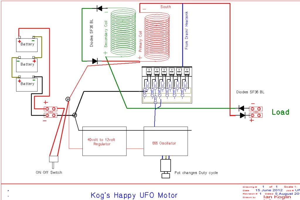
They are trying to build pretty much a Radiant energy circuit just like the vic circuit here.

What bugs me is - they are connecting it a different way:
Kogs Happy Motor


If we consider Primary Coil as inner Bobbin Coil and Secondary Coil as outer
Bobbin Coil. Load would be our Cell.

Could this be a better way to connect the bobbin, or are you already connecting it that way and i am totally wrong in understanding this hole thing?

Thanks for your attention.

PS: if i posted this to the wrong thread, just move it - thanks