Hello @all
I wanted to draw your attention to this forum:
http://www.energeticforum.com/renewable-energy/10529-my-motors-got-me-tap-into-radiant-energy-46.html
They are trying to build pretty much a Radiant energy circuit just like the vic circuit here.
What bugs me is - they are connecting it a different way:
If we consider Primary Coil as inner Bobbin Coil and Secondary Coil as outer
Bobbin Coil. Load would be our Cell.
Could this be a better way to connect the bobbin, or are you already connecting it that way and i am totally wrong in understanding this hole thing?
Thanks for your attention.
PS: if i posted this to the wrong thread, just move it - thanks
VIC Coil

Rider
RE: VIC Coil
« Reply #201, on December 1st, 2012, 02:58 AM »Last edited on December 1st, 2012, 02:59 AM by Rider
Hi Russ,
Sorry to bother you with some questions :
1. Did you get a change to rewind the coil yet and test it with the stainless steel coil windings connected. Arcing should not occur I guess due to the resistance of the SS wired coil? (Included with a diode)
2a. Is the attached the best design for the VIC coil? (Drawing from Stans bobbin with 14 cavities in WFC 423 DA)
2b. Do you know if anybody made a google sketchup drawing of this so I can order 3D printing from this drawing?
Thanks for the Scotch tape photo. I'll use this tape between coil windings and primary.
Regards, Rider
3d drawings for 13 cavity bobbins are here:
http://open-source-energy.org/?tid=565
14 cavity bobbins can be found here:
http://open-source-energy.org/?tid=365
Measurements in the Stan Meyer drawings show that 13 cavitys are correct, but there are 14 drawn in the diagram. Both are here for people to choose from.:D
I have a ways to go before I get my printers to print a high enough quality to print these again. Parts are wearing out. lol You can send the STL files to anyone with a printer or to a service like shapeways.
Nate
Rider
RE: VIC Coil
« Reply #203, on December 1st, 2012, 01:25 PM »Last edited on December 1st, 2012, 01:31 PM by Rider
3d drawings for 13 cavity bobbins are here:
http://open-source-energy.org/?tid=565
14 cavity bobbins can be found here:
http://open-source-energy.org/?tid=365
Measurements in the Stan Meyer drawings show that 13 cavitys are correct, but there are 14 drawn in the diagram. Both are here for people to choose from.:D
I have a ways to go before I get my printers to print a high enough quality to print these again. Parts are wearing out. lol You can send the STL files to anyone with a printer or to a service like shapeways.
Nate
IED
RE: VIC Coil
« Reply #204, on December 2nd, 2012, 03:18 PM »Last edited on December 2nd, 2012, 03:19 PM by IED-H2opower clone.
Hi Russ, I was sent a personal email by H2OPower a couple of months back, and if it is alright I would like to share what he told me,
Hi Jeff,
I saw your video and would like to welcome you to the world of Meyer now, LOL. In the designing of the WFC exciter array (ER) it is very important that you wire the capacitors up in series for that is how my Meyer used the ER as a part of the VIC circuit using water as a form of resistance. This drastically cuts the amps and allows voltage to take over. Here is a video I made showing the building of a 12 capacitor ER: https://www.youtube.com/watch?v=avtjOFc5Gdc
Now since I seem to be the first that has done this I am also the first to notice a problem other simply don't know about. In this next video you can see the problem: https://www.youtube.com/watch?v=4NrBEnRtHoE
It took me a few days to figure out what it was I was seeing and make sense of it. What you are seeing is a single phase set up and the effect of ionizing the water doesn't start to happen until around 215 volts. So now think of the voltage wave form and it becomes clear what it is you are seeing. As the voltage rises with each pulse it only will start to ionize the water once it reaches 215 volts and with the end of the pulse as the voltage drops below 215 volts the ionization of the water stops. That is what I think is taking place in my experiment as the time of the pulses don't change but only the voltage is being increased and the time that it is above 215 volts remains constant no mater how many volts I am above 215 volts, thus as seen in the video the pipe organ effect remains the same but the gas out put of those small time intervals goes up along with the increase in voltage.
Now the solution to fix this problem is three or more phases. Meyer used six phase and I will be to soon just as soon as I get the circuit up and running and make new VIC transformers for the ER. Meyer uses three phase and the VIC transformer action changes it into six phase as it acts as a frequency doubler. In this new set up the voltage will only drop 14% from the max voltage thus the water will be getting ionized at a far more constant rate than my one phase set up using the 8xa circuit.
If I had never of built the the series ER I would have never seen this problem. I guess in a way to protect his technology Meyer simple stop talking about the use of multiple phases even though he used 9 VIC transformers on his car when it was being run by the ER. The set up was in a three parallel three phase arrangement to a series ER.
In this video I just added a diode to the set up in the spot Meyer calls for an amp inhibiting coil and it increased efficiency as now the unit is only at .41 amps at above 1000 volts; https://www.youtube.com/watch?v=An35gDEo1b0 Since then I have increase that to 2k volts only drawing .33 amps. My first attempt at 3 phase didn't work so I am now back to the drawing board redesigning the circuit board with now a complete Meyer VIC driving circuit.
I go over a lot of the science behind Meyer's work one these two sites: http://www.hereticalbuilders.com/showthread.php?t=174 and http://open-source-energy.org/?tid=92
I hope this helps you become energy independent as I know that is both of our goals, enjoy!
And if you have more questions just ask away.
h2opower
Looks like good info, you be the judge, I thought I would post this info since h2opower deleted all that he had posted.
I also took the time to read his work at the other site and it does seem to make a lot of sense, making use of water as a resistor by wiring the cell up in series sure seems to have helped him out a lot. Anyway I was just wondering about this as I went through the thread looking at all that has been done by everyone.
IED
Does anybody know where to buy the laminated core for the VIC in europe?
I came across this vid, looks like a simple way to make a bobbin out of 2D materials.
https://www.youtube.com/watch?v=LE-vm7ZpKV8
https://www.youtube.com/watch?v=LE-vm7ZpKV8
Does anybody know where to buy the laminated core for the VIC in europe?
~russ
adys15
RE: VIC Coil
« Reply #208, on January 11th, 2013, 06:28 AM »Last edited on January 12th, 2013, 02:45 AM by ~Russ/Rwg42985
This is my first post here and I read the whole thread and was wondering if anyone else has gotten voltages this high to their cells as this guy h2opower is getting?
I also took the time to read his work at the other site and it does seem to make a lot of sense, making use of water as a resistor by wiring the cell up in series sure seems to have helped him out a lot. Anyway I was just wondering about this as I went through the thread looking at all that has been done by everyone.
IED
Jeff Nading
RE: VIC Coil
« Reply #209, on January 11th, 2013, 06:33 AM »Last edited on January 12th, 2013, 02:45 AM by ~Russ/Rwg42985
This is my first post here and I read the whole thread and was wondering if anyone else has gotten voltages this high to their cells as this guy h2opower is getting?
I also took the time to read his work at the other site and it does seem to make a lot of sense, making use of water as a resistor by wiring the cell up in series sure seems to have helped him out a lot. Anyway I was just wondering about this as I went through the thread looking at all that has been done by everyone.
IED
30v is not HV anyway....look at Max last video,43v with 1 tubeset
~Russ
RE: VIC Coil
« Reply #210, on January 12th, 2013, 02:44 AM »Last edited on January 12th, 2013, 02:45 AM by ~Russ/Rwg42985
30v is not HV anyway....look at Max last video,43v with 1 tubesetQuote from adys15 on January 11th, 2013, 06:28 AM This is my first post here and I read the whole thread and was wondering if anyone else has gotten voltages this high to their cells as this guy h2opower is getting?
I also took the time to read his work at the other site and it does seem to make a lot of sense, making use of water as a resistor by wiring the cell up in series sure seems to have helped him out a lot. Anyway I was just wondering about this as I went through the thread looking at all that has been done by everyone.
IED
Russ has gotten higher voltages, I don't remember what though.:D
Hi everybody
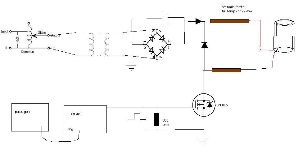
I am building a Stan meyer WFC, The circuit i have built is a basic ravi or lawton type circuit using wound ferrite rods , i have got it into resonance at around 1.5mhz which i think is way too high as the coils capacitance and inductance is too low, i am getting a very good waveform however, pure sine and getting about 70 - 100v on the L1 inductor and better than DC gas production.
has anybody got some values of resonance of the VIC connected to a cell, the square type one with the tripple 4000 turn coils and the rectangular ferrite setup like this -
http://www.globalkast.com/docs/VIC_Transformer_&_Cavity.pdf
i was trying to get in contact with vaylonpz as he has a you-tube video showing a very good setup
Cheers people
Hi everybody
I am building a Stan meyer WFC, The circuit i have built is a basic ravi or lawton type circuit using wound ferrite rods , i have got it into resonance at around 1.5mhz which i think is way too high as the coils capacitance and inductance is too low, i am getting a very good waveform however, pure sine and getting about 70 - 100v on the L1 inductor and better than DC gas production.
has anybody got some values of resonance of the VIC connected to a cell, the square type one with the tripple 4000 turn coils and the rectangular ferrite setup like this -
http://www.globalkast.com/docs/VIC_Transformer_&_Cavity.pdf
i was trying to get in contact with vaylonpz as he has a you-tube video showing a very good setup
Cheers people
No not from a 555 tried that first and hated it they are just too slow in every respect the rise and fall time is too slow, its the same driver circuit driven from a tektronics signal generator driven with a pulse generator, the rise and fall is less than 6ns, over 10ns and it stops resonating all together. the mosfet was taken out of an old power supply and so are the diodes one de Qing and the other across the input on the two coils,
Initialy my multimeter told me at under resonance i was drawing 2ma, I connected up an analogue one and it was around 200ma the voltage is controlled buy a vairiac into an isolation Transformer to DC across a cap, strangely the voltage will alter the thing resonating, if you change V you have to re tune the F
Gas production is pretty low i would say no where near what it should be, but compared to the same amps on the gauge, id say about 5x the output, not really a very good comparison tho.
Tony is his username on here? so his resonance is about 5khz then, thats what im looking for, i have heard that the coils on the right side are about 11khz resonant from calculations.
Cheers
Hi everybody
I am building a Stan meyer WFC, The circuit i have built is a basic ravi or lawton type circuit using wound ferrite rods , i have got it into resonance at around 1.5mhz which i think is way too high as the coils capacitance and inductance is too low, i am getting a very good waveform however, pure sine and getting about 70 - 100v on the L1 inductor and better than DC gas production.
has anybody got some values of resonance of the VIC connected to a cell, the square type one with the tripple 4000 turn coils and the rectangular ferrite setup like this -
http://www.globalkast.com/docs/VIC_Transformer_&_Cavity.pdf
i was trying to get in contact with vaylonpz as he has a you-tube video showing a very good setup
Cheers people
30v is not HV anyway....look at Max last video,43v with 1 tubesetQuote This is my first post here and I read the whole thread and was wondering if anyone else has gotten voltages this high to their cells as this guy h2opower is getting?
I also took the time to read his work at the other site and it does seem to make a lot of sense, making use of water as a resistor by wiring the cell up in series sure seems to have helped him out a lot. Anyway I was just wondering about this as I went through the thread looking at all that has been done by everyone.
IED
https://www.youtube.com/watch?v=003TrflPvqY&lc=3bPSBg8editGCSAWn45oJRGUPFSEeAz7lqppAeyIjKY
Check out this video by Max Miller
Awesome work on this project !
HHO IS REAL
https://www.youtube.com/watch?v=003TrflPvqY&lc=3bPSBg8editGCSAWn45oJRGUPFSEeAz7lqppAeyIjKY
Check out this video by Max Miller
Awesome work on this project !
HHO IS REAL
[/quote]Well, it's just at I thought no one in the whole world has gotten voltages that high as I don't by "I don't know" but I was just curious to see if anyone else has had that kind of luck with Meyer's work other than h2opower, so I would guess the answer to be no.[/quote]Tony get hv over the wfc....Some guys from ionizationx got hv...i also got hv with distiled water and a larger gap...but the problem is you dont get the production to high as you aspected...I think hv in Stans words is misleading...you can get hv on the cell but that hv has ''no work''...
Webmug
RE: VIC Coil
« Reply #221, on February 8th, 2013, 02:58 AM »Last edited on February 8th, 2013, 03:19 AM by Webmug
https://www.youtube.com/watch?v=003TrflPvqY&lc=3bPSBg8editGCSAWn45oJRGUPFSEeAz7lqppAeyIjKY
Check out this video by Max Miller
Awesome work on this project !
HHO IS REAL
https://www.youtube.com/watch?v=DpwDdzEkiZE
30V 300mA!!!!!!
/watch?v=hVn_TRH59lI
242V!!!!!!!!
Regards,
Webmug
He's not open source.Quote from Dog-One on February 6th, 2013, 07:59 PM Think you can get irondmax's full specs so we can replicate?Quote from hydrofuelincanada on February 6th, 2013, 07:48 PM
https://www.youtube.com/watch?v=003TrflPvqY&lc=3bPSBg8editGCSAWn45oJRGUPFSEeAz7lqppAeyIjKY
Check out this video by Max Miller
Awesome work on this project !
HHO IS REAL
maybe he is open source and you never watched his video on how to do that!Quote from Jeff Nading on February 6th, 2013, 08:00 PM He's not open source.Quote from Dog-One on February 6th, 2013, 07:59 PM Think you can get irondmax's full specs so we can replicate?Quote from hydrofuelincanada on February 6th, 2013, 07:48 PM
https://www.youtube.com/watch?v=003TrflPvqY&lc=3bPSBg8editGCSAWn45oJRGUPFSEeAz7lqppAeyIjKY
Check out this video by Max Miller
Awesome work on this project !
HHO IS REAL
Although the intention is good sometimes we get mixed up.
Overall what Max is doing is trying to get people the items they need to replicate Stanmeyer's things. Although some of us don't agree that selling things that aren't proven might be a bad idea the person selling them as ability to do so or not. That is their choice. Whether it's good or bad in your eyes let's still play nice...
The diagrams aren't necessarily posted next to the circuits being sold
Nonetheless what Max and Per and the rest of them are trying to do is bring in the replicated circuits at a decent price.
Max isn't a bad guy. What he's doing is definitely different than what We are doing but over all the goal is the same.
Anyway I guess what I'm trying to say is let's just stick to what we know and if max wants to post what you have requested here great if not So be it...
Anyway all play nice just another day in paradise...
~Russ
hydrofuelincanada
RE: VIC Coil
« Reply #224, on February 8th, 2013, 05:32 AM »Last edited on February 8th, 2013, 05:38 AM by hydrofuelincanada- was asked to be removed
maybe he is open source and you never watched his video on how to do that!Quote from Jeff Nading on February 6th, 2013, 08:00 PM He's not open source.Quote from Dog-One on February 6th, 2013, 07:59 PM Think you can get irondmax's full specs so we can replicate?Quote from hydrofuelincanada on February 6th, 2013, 07:48 PM
https://www.youtube.com/watch?v=003TrflPvqY&lc=3bPSBg8editGCSAWn45oJRGUPFSEeAz7lqppAeyIjKY
Check out this video by Max Miller
Awesome work on this project !
HHO IS REAL
Project Icarus is not allowed to post his work here because he sells stuff, No one is allowed to post here if they sell stuff.
maybe he is open source and you never watched his video on how to do that!Quote from Jeff Nading on February 6th, 2013, 08:00 PM He's not open source.Quote from Dog-One on February 6th, 2013, 07:59 PM Think you can get irondmax's full specs so we can replicate?Quote from hydrofuelincanada on February 6th, 2013, 07:48 PM
https://www.youtube.com/watch?v=003TrflPvqY&lc=3bPSBg8editGCSAWn45oJRGUPFSEeAz7lqppAeyIjKY
Check out this video by Max Miller
Awesome work on this project !
HHO IS REAL