Let's build A "Popper" Noble Gas Engine AKA Ppap Engine.

Babble

RE: Let's build A "Popper" Noble Gas Engine AKA Ppap Engine.
« Reply #1675, on February 10th, 2013, 10:04 PM »
Quote from ~Russ/Rwg42985 on February 9th, 2013, 09:31 PM
Quote from Babble on February 8th, 2013, 12:56 PM
You guys can ignore this again but to get a high current rise time on the 350V DC arc you need to reduce inductance first.  This can be done by using twisted wires from the cap bank to the contacts.  The second thing is to use a HV mylar cap right at the terminals of the arc contacts on the engine.  This will provide the initial fast rise time that gives the main current a chance to catch up.  I would suggest a cap like Mouser part number 598-935C4W3-2K-F  which is 3uF/400V rated for high current.  If you plan to go higher than 400V then I would get a higher voltage rating.
we did not ignore it. or at least i did not. :)

~Russ

PS i have 165,000uf in the bank i'm using now. to get that with theses caps i would need 55,000 of them. thats @ 1,000 for $1.03 each you do the math. lol

but your right making a bank would be a grate idea.

i will try the wisted wires idea i remember when you stated this the first time. but i haven't tested sense then.. :) will try it.
Russ, why are you building such a large cap bank (50 x 3300uF)?  I was suggesting using just one of the Mylar caps at the terminals.  This would provide initial very fast rise time until the larger caps over come the inductance of the wire.  I think you need to use less energy because controlling this large a pulse is never going to work for an engine and it can be dangerous.  The data sheet said the ESR was 30 mOhms each (A capital M means meg) so 50 in parallel is 0.6 mOhms max.  This could be a peak pulse current of 583,000 amps when charged to 350 V.  Something will blow.

~Russ

RE: Let's build A "Popper" Noble Gas Engine AKA Ppap Engine.
« Reply #1676, on February 11th, 2013, 03:10 AM »Last edited on February 11th, 2013, 05:06 AM by ~Russ/Rwg42985
Quote from Babble on February 10th, 2013, 10:04 PM
Quote from ~Russ/Rwg42985 on February 9th, 2013, 09:31 PM
Quote from Babble on February 8th, 2013, 12:56 PM
You guys can ignore this again but to get a high current rise time on the 350V DC arc you need to reduce inductance first.  This can be done by using twisted wires from the cap bank to the contacts.  The second thing is to use a HV mylar cap right at the terminals of the arc contacts on the engine.  This will provide the initial fast rise time that gives the main current a chance to catch up.  I would suggest a cap like Mouser part number 598-935C4W3-2K-F  which is 3uF/400V rated for high current.  If you plan to go higher than 400V then I would get a higher voltage rating.
we did not ignore it. or at least i did not. :)

~Russ

PS i have 165,000uf in the bank i'm using now. to get that with theses caps i would need 55,000 of them. thats @ 1,000 for $1.03 each you do the math. lol

but your right making a bank would be a grate idea.

i will try the wisted wires idea i remember when you stated this the first time. but i haven't tested sense then.. :) will try it.
Russ, why are you building such a large cap bank (50 x 3300uF)?  I was suggesting using just one of the Mylar caps at the terminals.  This would provide initial very fast rise time until the larger caps over come the inductance of the wire.  I think you need to use less energy because controlling this large a pulse is never going to work for an engine and it can be dangerous.  The data sheet said the ESR was 30 mOhms each (A capital M means meg) so 50 in parallel is 0.6 mOhms max.  This could be a peak pulse current of 583,000 amps when charged to 350 V.  Something will blow.
well the main answer for your question is that i was going to get 5 of theses but at the price was given i picked up some extra.

so the testing most likely will be done with one bank of 5 or if i need higher voltages i can series up some banks of 5...

the bank of 50 is for other projects:

http://open-source-energy.org/?tid=805

at a ridicules price i just got extra crazy... lol
better to have more than enough...

so that may help answer your question.

trying to stay under 1000J for testing. but if we can control the short pulse then we may be better off storing a lot of energy and popping small amounts in at a time... and then replenishing the lost energy slowly. also. i thought is was 20Mohm, and yes i know M is mega. i was calculating the ESR as if it was a resistance so if there parallel then... ( )

 ??
please correct me if i'm wrong. oh, and i'm not disagreeing with the caps you picked as a good contender. they are. i'm just using what i have... :)
~Russ


Babble

RE: Let's build A "Popper" Noble Gas Engine AKA Ppap Engine.
« Reply #1677, on February 12th, 2013, 02:46 PM »
Quote from ~Russ/Rwg42985 on February 11th, 2013, 03:10 AM
Quote from Babble on February 10th, 2013, 10:04 PM
Quote from ~Russ/Rwg42985 on February 9th, 2013, 09:31 PM
Quote from Babble on February 8th, 2013, 12:56 PM
You guys can ignore this again but to get a high current rise time on the 350V DC arc you need to reduce inductance first.  This can be done by using twisted wires from the cap bank to the contacts.  The second thing is to use a HV mylar cap right at the terminals of the arc contacts on the engine.  This will provide the initial fast rise time that gives the main current a chance to catch up.  I would suggest a cap like Mouser part number 598-935C4W3-2K-F  which is 3uF/400V rated for high current.  If you plan to go higher than 400V then I would get a higher voltage rating.
we did not ignore it. or at least i did not. :)

~Russ


PS i have 165,000uf in the bank i'm using now. to get that with theses caps i would need 55,000 of them. thats @ 1,000 for $1.03 each you do the math. lol

but your right making a bank would be a grate idea.

i will try the wisted wires idea i remember when you stated this the first time. but i haven't tested sense then.. :) will try it.
Russ, why are you building such a large cap bank (50 x 3300uF)?  I was suggesting using just one of the Mylar caps at the terminals.  This would provide initial very fast rise time until the larger caps over come the inductance of the wire.  I think you need to use less energy because controlling this large a pulse is never going to work for an engine and it can be dangerous.  The data sheet said the ESR was 30 mOhms each (A capital M means meg) so 50 in parallel is 0.6 mOhms max.  This could be a peak pulse current of 583,000 amps when charged to 350 V.  Something will blow.
well the main answer for your question is that i was going to get 5 of theses but at the price was given i picked up some extra.

so the testing most likely will be done with one bank of 5 or if i need higher voltages i can series up some banks of 5...

the bank of 50 is for other projects:

http://open-source-energy.org/?tid=805

at a ridicules price i just got extra crazy... lol
better to have more than enough...

so that may help answer your question.

trying to stay under 1000J for testing. but if we can control the short pulse then we may be better off storing a lot of energy and popping small amounts in at a time... and then replenishing the lost energy slowly. also. i thought is was 20Mohm, and yes i know M is mega. i was calculating the ESR as if it was a resistance so if there parallel then... ( )

 ??
please correct me if i'm wrong. oh, and i'm not disagreeing with the caps you picked as a good contender. they are. i'm just using what i have... :)
~Russ
Russ, you have me worried, thinking you were going to use all those caps at once.   There are other limiting factors including the wire resistance.  You're an experimenter so getting a bunch of them is probably a good deal.  I was addressing how to get a fast rise time because that was being discussed.  

Since all the caps have the same max ESR, just divide it by the number of caps.   For various parallel resistors you have the right formula.   Run a calculator test using 30 ohms,  30 1/x, + 30 1/x + 30 1/x = 1/x .  You'll get 10 ohms which is 30 /3 resistors.

Looking at 3300uF, 350V I saw 30 milli ohms but maybe I read something wrong.
Be safe.

FaradayEZ

RE: Let's build A "Popper" Noble Gas Engine AKA Ppap Engine.
« Reply #1678, on February 13th, 2013, 02:06 PM »
Quote from ~Russ/Rwg42985 on February 11th, 2013, 03:10 AM
well the main answer for your question is that i was going to get 5 of theses but at the price was given i picked up some extra.

so the testing most likely will be done with one bank of 5 or if i need higher voltages i can series up some banks of 5...
One interesting test with the popper you can do with it.

If you can measure the output force of the plasmoid reaction per input in current and voltage, we can find out some optimum points and see what line the output versus input makes with actual test data.

More voltage more power, but in what ratio, what relation. A straight line graph? Not likely.


Matt Watts

RE: Let's build A "Popper" Noble Gas Engine AKA Ppap Engine.
« Reply #1679, on February 13th, 2013, 05:36 PM »
Quote from FaradayEZ on February 13th, 2013, 02:06 PM
If you can measure the output force of the plasmoid reaction per input in current and voltage, we can find out some optimum points and see what line the output versus input makes with actual test data.

More voltage more power, but in what ratio, what relation. A straight line graph? Not likely.
Bet most anything it isn't linear--probably exponential.  When you get close to something you would call overunity, a little more and it blows up.  Which means, some very precise sensors are in order.  If your resolution isn't good enough, one would likely end up wearing their popper on their face.

FaradayEZ

RE: Let's build A "Popper" Noble Gas Engine AKA Ppap Engine.
« Reply #1680, on February 14th, 2013, 12:23 AM »
Quote from Dog-One on February 13th, 2013, 05:36 PM
Quote from FaradayEZ on February 13th, 2013, 02:06 PM
If you can measure the output force of the plasmoid reaction per input in current and voltage, we can find out some optimum points and see what line the output versus input makes with actual test data.

More voltage more power, but in what ratio, what relation. A straight line graph? Not likely.
Bet most anything it isn't linear--probably exponential.  When you get close to something you would call overunity, a little more and it blows up.  Which means, some very precise sensors are in order.  If your resolution isn't good enough, one would likely end up wearing their popper on their face.
Yeah, Papp always used a dangerous mix, he was not able to tune it down to a more safe potion. Like a gasoline vapor only has so much energy and won't likely blow up an engine. So the O.U. Papp mixture always will have the volatile side.

At least until we understand it more then he did. And would be able to find something to make it more save.

And or else, what restrictions on volt/amperidge input can be made that would satisfy the government agencies on vehicles?

And would it stay working after a collision?


~Russ

RE: Let's build A "Popper" Noble Gas Engine AKA Ppap Engine.
« Reply #1681, on February 14th, 2013, 02:15 AM »Last edited on February 14th, 2013, 02:18 AM by ~Russ/Rwg42985
Quote from Babble on February 12th, 2013, 02:46 PM
Quote from ~Russ/Rwg42985 on February 11th, 2013, 03:10 AM
Quote from Babble on February 10th, 2013, 10:04 PM
Quote from ~Russ/Rwg42985 on February 9th, 2013, 09:31 PM
Quote from Babble on February 8th, 2013, 12:56 PM
You guys can ignore this again but to get a high current rise time on the 350V DC arc you need to reduce inductance first.  This can be done by using twisted wires from the cap bank to the contacts.  The second thing is to use a HV mylar cap right at the terminals of the arc contacts on the engine.  This will provide the initial fast rise time that gives the main current a chance to catch up.  I would suggest a cap like Mouser part number 598-935C4W3-2K-F  which is 3uF/400V rated for high current.  If you plan to go higher than 400V then I would get a higher voltage rating.
we did not ignore it. or at least i did not. :)

~Russ


PS i have 165,000uf in the bank i'm using now. to get that with theses caps i would need 55,000 of them. thats @ 1,000 for $1.03 each you do the math. lol

but your right making a bank would be a grate idea.

i will try the wisted wires idea i remember when you stated this the first time. but i haven't tested sense then.. :) will try it.
Russ, why are you building such a large cap bank (50 x 3300uF)?  I was suggesting using just one of the Mylar caps at the terminals.  This would provide initial very fast rise time until the larger caps over come the inductance of the wire.  I think you need to use less energy because controlling this large a pulse is never going to work for an engine and it can be dangerous.  The data sheet said the ESR was 30 mOhms each (A capital M means meg) so 50 in parallel is 0.6 mOhms max.  This could be a peak pulse current of 583,000 amps when charged to 350 V.  Something will blow.
well the main answer for your question is that i was going to get 5 of theses but at the price was given i picked up some extra.

so the testing most likely will be done with one bank of 5 or if i need higher voltages i can series up some banks of 5...

the bank of 50 is for other projects:

http://open-source-energy.org/?tid=805

at a ridicules price i just got extra crazy... lol
better to have more than enough...

so that may help answer your question.

trying to stay under 1000J for testing. but if we can control the short pulse then we may be better off storing a lot of energy and popping small amounts in at a time... and then replenishing the lost energy slowly. also. i thought is was 20Mohm, and yes i know M is mega. i was calculating the ESR as if it was a resistance so if there parallel then... ( )

 ??
please correct me if i'm wrong. oh, and i'm not disagreeing with the caps you picked as a good contender. they are. i'm just using what i have... :)
~Russ
Russ, you have me worried, thinking you were going to use all those caps at once.   There are other limiting factors including the wire resistance.  You're an experimenter so getting a bunch of them is probably a good deal.  I was addressing how to get a fast rise time because that was being discussed.  

Since all the caps have the same max ESR, just divide it by the number of caps.   For various parallel resistors you have the right formula.   Run a calculator test using 30 ohms,  30 1/x, + 30 1/x + 30 1/x = 1/x .  You'll get 10 ohms which is 30 /3 resistors.

Looking at 3300uF, 350V I saw 30 milli ohms but maybe I read something wrong.
Be safe.
i must have lost my mined... yes i see its 30Mohm... :)

ahhh... sleep... that's a good thing.. :)  where can i get some of that!


~Russ

atanguy

RE: Let's build A "Popper" Noble Gas Engine AKA Ppap Engine.
« Reply #1682, on February 14th, 2013, 08:53 PM »
 I'm following the edition of "Primer Fields" on youtube by David Lapoint:
   Part#1: https://www.youtube.com/watch?v=siMFfNhn6dk
   Part#2: https://www.youtube.com/watch?v=2NogyJ0k8Kw
   Part#3: https://www.youtube.com/watch?v=lpI6ikj1G-s
   It demonstrates some radical ideas in Physic about magnetic bowl shaped fields being the center of everything in matter from atoms to galaxies. Using plasmoid experiment produced in the lab and comparing results to astrophysics phenomena.
   One sequence on Part#1 38'30"- 39'15"  shows the ejection of a small magnet from a magnetic field of a bowl that could be a possible explanation of the Papp engine (I remember Russ talking about the shape of the base of the piston, that look like one of these bowls... ). Anybody thought?

~Russ

RE: Let's build A "Popper" Noble Gas Engine AKA Ppap Engine.
« Reply #1683, on February 15th, 2013, 02:21 AM »Last edited on February 15th, 2013, 02:22 AM by ~Russ/Rwg42985
Quote from atanguy on February 14th, 2013, 08:53 PM
I'm following the edition of "Primer Fields" on youtube by David Lapoint:
   Part#1: https://www.youtube.com/watch?v=siMFfNhn6dk
   Part#2: https://www.youtube.com/watch?v=2NogyJ0k8Kw
   Part#3: https://www.youtube.com/watch?v=lpI6ikj1G-s
   It demonstrates some radical ideas in Physic about magnetic bowl shaped fields being the center of everything in matter from atoms to galaxies. Using plasmoid experiment produced in the lab and comparing results to astrophysics phenomena.
   One sequence on Part#1 38'30"- 39'15"  shows the ejection of a small magnet from a magnetic field of a bowl that could be a possible explanation of the Papp engine (I remember Russ talking about the shape of the base of the piston, that look like one of these bowls... ). Anybody thought?
yes, thses videos are also posted here:

http://open-source-energy.org/?tid=1011

i would replay of off topic Primer Fields there.

but yes, a lot of interesting and if nothing else cool plasma demonstrations. his theory's are interesting.

we have discussed some of these in the past. but over all its kinda not relevant...

just watching the plasma is extremely cool tho.

thanks ~Russ

Willard Elliott

RE: Let's build A "Popper" Noble Gas Engine AKA Ppap Engine.
« Reply #1684, on February 15th, 2013, 03:11 PM »


To Russ and the group


I i
just read in Wikapedia that 1N4007 diodes make a good X-Ray detector.

Several in series connected to an oscilloscope will provide a voltage when in an X-Ray beem[/font][/size]

Willard Elliott

RE: Let's build A "Popper" Noble Gas Engine AKA Ppap Engine.
« Reply #1685, on February 16th, 2013, 09:33 AM »


I am most impressed by your green afterglow in your air and argon gas in the clear glass pressure chamber. The 9 to 11 frame stills show a lot that is going on in the Papp prossces. Keep up the good work Russ!

I am confused by the Rohner patent application.  It does not show any use of a lower voltage high current in the spark gaps. It has only the 4 spark plugs operating at 55 KV. Presumably  two are in reverse as he states that they create a 140 KV  arc of a long enough duration to transition the gas. This must be what allows for his over 1000 to one difference from power input to hosepower out. It is stated in their video that consumption is only a total of about 160 watts while the motor puts out 274 horsepower. 274 X 746 = 204,404 watts. All other patents use the HV spark only to ionize the gas then follow it with a high current low voltage spark (160 to 500 volt).

I am a builder and intend to build several engines running on Plasma gas.

Are theer others in the group who are intending to build motors?

Best Regards,
Willard


k c dias

RE: Let's build A "Popper" Noble Gas Engine AKA Ppap Engine.
« Reply #1686, on February 16th, 2013, 10:52 AM »Last edited on February 16th, 2013, 10:57 AM by k c dias
Quote from Willard Elliott on February 16th, 2013, 09:33 AM


I am most impressed by your green afterglow in your air and argon gas in the clear glass pressure chamber. The 9 to 11 frame stills show a lot that is going on in the Papp prossces. Keep up the good work Russ!

I am confused by the Rohner patent application.  It does not show any use of a lower voltage high current in the spark gaps. It has only the 4 spark plugs operating at 55 KV. Presumably  two are in reverse as he states that they create a 140 KV  arc of a long enough duration to transition the gas. This must be what allows for his over 1000 to one difference from power input to hosepower out. It is stated in their video that consumption is only a total of about 160 watts while the motor puts out 274 horsepower. 274 X 746 = 204,404 watts. All other patents use the HV spark only to ionize the gas then follow it with a high current low voltage spark (160 to 500 volt).

I am a builder and intend to build several engines running on Plasma gas.

Are theer others in the group who are intending to build motors?

Best Regards,
Willard
PTP is a complete HOAX.  Forget you ever read the Plasmerg patent application, totally useless bullsh!t (IMHO).  The Papp engine, on the other hand, was real.  Do stick around and watch this thread and others.  I believe the true process behind the Papp engine will emerge, and possibly soon.

kcd


Babble

RE: Let's build A "Popper" Noble Gas Engine AKA Ppap Engine.
« Reply #1687, on February 16th, 2013, 11:54 AM »
Quote from Willard Elliott on February 15th, 2013, 03:11 PM


To Russ and the group


I i
just read in Wikapedia that 1N4007 diodes make a good X-Ray detector.

Several in series connected to an oscilloscope will provide a voltage when in an X-Ray beem[/font][/size]
Interesting, never heard of that but if the 1N4007 works, then probably the 1N4148 would work even better since it is a high frequency signal diode.
http://en.wikipedia.org/wiki/1N4148


Willard Elliott

RE: Let's build A "Popper" Noble Gas Engine AKA Ppap Engine.
« Reply #1689, on February 16th, 2013, 03:01 PM »Last edited on February 16th, 2013, 03:25 PM by Willard Elliott
The 1N4007 diode X-Ray detector can be calibrated by using any luminous watch or clock dial.
Best regards,

Willard
To KCD

The expansion of the gas seems to be an avalanche prosses as I note that when the voltage is close to too low the flash starts late but nevertheless is complet with full volume or pressure increas. However the pull back is at least 10 times longer. It is seemingly an exponential curve. Unless this can be speeded up it makes it useless to use a crankshaft as both strokes have to be approximately equal. The observed phenomena is much better applied to a diaphragm type compressor. The diaphragm can be Teflon. The other side of the diaphragm can feed an air tank with appropriat check valves. Rotary power can then be any steam engine running off of the compressed air.

Best regards,

Willard


Axil

RE: Let's build A "Popper" Noble Gas Engine AKA Ppap Engine.
« Reply #1691, on February 19th, 2013, 01:44 PM »Last edited on February 19th, 2013, 04:58 PM by Axil
The thread started by k c dias discribing the clem engine has got me excited. It may be possible to develop a hybrid Clem/Papp engine.

How this hybrid might be configured as follows:

But some background about recent LENR system experimentation describing a new kind of energy-producing device was announced at the 12th International Conference on Cold fusion by Hyunik Yang of Hangyang University in South Korea and his colleagues.

The device as presented is basically a closed loop around which oil is pumped, and forced through a plastic nozzle near Mach 1. In association with the oil flow, a discharge develops in the vicinity of the nozzle, which is readily seen by eye.

The simplest version of the cell looks something like a vintori tube.


Oil flows in under pressure on the left, into the cell where it is forced through a nozzle inside the cell, and then exits on the right.

The basic claim associated with excess heat as presented at ICCF12 involves a comparison of the thermal power, as determined from thermal and pressure measurements taken on either side of the cell combined with measurements of the flow velocity, to the electrical power input to the pump.

In response to a videotape of the device, Tom Dolan provided the following narrative: "A boron-doped oil at 30 atm appeared to have a color that is tawny; and that at over 40 atm, it is white; while at over 60 atm it is clear, with a plasma jet downstream of the orifice. At 70-80 atm, there is a bright blue beam 6 mm in diameter, and at over 90 atm a green glow appears upstream of the orifice. Hard X-rays were observed from the luminous region. The researchers claim that excess heat is generated from fusion reactions (possibly protons plus boron-11) during the collapse of cavitation bubbles, and they [claim to have] detected He-4 emission lines from the cavitating fluid."


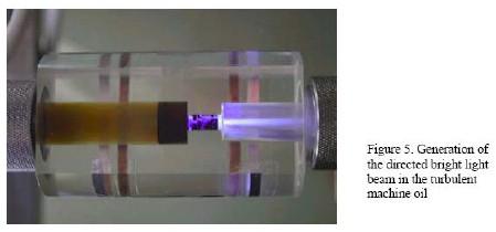
When running, a discharge appears in the cell. In addition, cavitation bubbles are observed in the oil flow on the exit side of the cell. Hard x-rays were observed from the luminous region. The researchers claim that excess heat is generated from fusion reactions (possibly protons plus boron-11) during collapse of cavitation bubbles, and they detected He-4 emission lines from the cavitating fluid.

Proposal for a hybrid Papp engine

A hybrid system is proposed to combine the Papp engine with the Yang device as follows:

A dielectric mineral oil will produce superatomic clusters when subjected to supersonic decompression through a pinhole nozzle. When so processed at sufficiently high pressures; the oil will vaporize into a gas.

If a supersonic fuel injector is added to the Papp engine which includes a mix of noble gases, this vaporized mineral oil gas discharge will catalyze superatomic cluster formation in these noble gases when the oil vapor stream enters into the noble gas envelop from the head of the high pressure oil injection supersonic nozzle. If no oxygen is present, combustion of the oil vapor does not occur and no oil is consumed.

One development that makes this hybrid possible at the current time is the development of a high pressure fuel injector that can produce a pressure of 160,000 PSI or 11031 atmospheres.

Compared to the 100 atmospheres required by the Yang device (about 100 times more), there is more than enough pressure needed to vaporize the mineral oil into cavatation bubble production.

http://www.dieselpowermag.com/tech/0905dp_green_diesel_corp_fuel_injectors/

http://blogs.dieselpowermag.com/6636119/diesel-engines/diesel-power-helps-green-diesel-corp-secure-30-million-deal/

In this plan, the fuel injector would fire just before the plasmoid discharge. The plasmoid would excite ion explosion in the oil/noble gas mix to provide a pressure pulse to the cylinder head without any consumption of the mineral oil.

Excess noble gas clusters (also boron if added) not subject to ion exposition produced by the plasmoid would enrich the oil over time and be carried in the oil sump at the bottom of the cylinder.

Additives could be added to the oil and noble gas envelope for the purpose of experimentation. This includes hydrogen, boron, and deuterium.  

Patent for the 160,000 PSI fuel injector.

http://www.rexresearch.com/kukler/kukler.htm

Video


https://www.youtube.com/watch?v=aZH0bbpswlA

Company Name:    green diesel corp

Contact Person:    ron kukler

About Us:    pollution free diesel fuel injection systems
   
Country:    Australia

Company Overview

GREEN DIESEL CORP LTD.

designs, develops, and manufactures pressure fuel injection system for diesel and other liquid fuel engines. Its fuel injection system allows petrol to diesel conversions. The company was incorporated in 2002 and is based in Melbourne, Australia. As of June 30, 2012, GREEN DIESEL CORP LTD. operates as a subsidiary of Astra Mining Pty Ltd.

Level 4

179 Queen St
Melbourne, TAS 3000
Australia

Founded in 2002

Phone:    +61 4 0284 6986
Fax:           61 3 5244 0858

www.greendieselcorp.com


Matt Watts

RE: Let's build A "Popper" Noble Gas Engine AKA Ppap Engine.
« Reply #1692, on February 19th, 2013, 03:50 PM »
Quote from Axil on February 19th, 2013, 01:44 PM
In this plan, the fuel injector would fire just before the plasmoid discharge. The plasmoid would excite ion explosion in the oil/noble gas mix to provide a pressure pulse to the cylinder head without any consumption of the mineral oil.

Excess noble gas clusters (also boron if added) not subject to ion exposition produced by the plasmoid would enrich the oil over time and be carried in the oil sump at the bottom of the cylinder.
Mechanically, it would seem to me we would want a partial ICE--no intake valve, but we would want an exhaust valve where the oil vapor could be reclaimed, cooled, filtered, doped and re-introduced to the injector.  Modification of a typical petroleum engine I would think would be to change the intake cam lobe and just use both the intake and exhaust valves/ports as exhaust.  Unlike the Papp sealed design, I like the idea of having a way to scavenge the combustion chamber repetitively so we always have the proper mix available.  This also makes throttle control much more easy in the process.

Axil, do you have a rough estimate of the power consumption required by the injector unit?  How about expansion rate so an optimal bore to stroke ratio can be obtained?

edxhemphill

RE: Let's build A "Popper" Noble Gas Engine AKA Ppap Engine.
« Reply #1693, on February 19th, 2013, 03:59 PM »
Hi Willard , You ask if any one else is a builder and the answer is yes. I have built a variation of the ptp engine as has K C Dias That I know of. I to , was a tv repairman /electronic tech.Don't waste your time or money doing any thing like ptp says.If you duplicate the Papp engine you may do better but please be carfull as it can be very explosive !If you would like to talk please call me after 9 and before 9 pm central time at 830 708 7007  Ed Hemphill  

Axil

RE: Let's build A "Popper" Noble Gas Engine AKA Ppap Engine.
« Reply #1694, on February 19th, 2013, 06:20 PM »
Quote from Dog-One on February 19th, 2013, 03:50 PM
Quote from Axil on February 19th, 2013, 01:44 PM
In this plan, the fuel injector would fire just before the plasmoid discharge. The plasmoid would excite ion explosion in the oil/noble gas mix to provide a pressure pulse to the cylinder head without any consumption of the mineral oil.

Excess noble gas clusters (also boron if added) not subject to ion exposition produced by the plasmoid would enrich the oil over time and be carried in the oil sump at the bottom of the cylinder.
Mechanically, it would seem to me we would want a partial ICE--no intake valve, but we would want an exhaust valve where the oil vapor could be reclaimed, cooled, filtered, doped and re-introduced to the injector.  Modification of a typical petroleum engine I would think would be to change the intake cam lobe and just use both the intake and exhaust valves/ports as exhaust.  Unlike the Papp sealed design, I like the idea of having a way to scavenge the combustion chamber repetitively so we always have the proper mix available.  This also makes throttle control much more easy in the process.

Axil, do you have a rough estimate of the power consumption required by the injector unit?  How about expansion rate so an optimal bore to stroke ratio can be obtained?
Dog,

Thanks for your interest in this idea.

The green injector is individually electrically powered and I doubt that its energy consumption is high because it operates in a pulsed mode.

Just like the baseline Papp engine, I also doubt that this hybrid Papp engine would generate an elevated level of heat because no combustion takes place. The supersonic oil stream of oil from the injector should cool the oil.

The compression of the oil inside the injector might produce heat, but that heat might well be isolated from the Papp cylinder and removed by smart cooling of the injector; a fluid cooling design or a heat pipe might provide injector cooling.  


The pump that feeds oil to the injector from the oil sump  would be a low powered affair requiring little power and producing little heat.


There is a chance that the hybrid engine cylinder will operate in a way that is similar if not identically to the way the baseline Papp engine operates with little if any mechanical modifications required.


~Russ

RE: Let's build A "Popper" Noble Gas Engine AKA Ppap Engine.
« Reply #1696, on February 19th, 2013, 11:29 PM »
Quote from edxhemphill on February 19th, 2013, 03:59 PM
Hi Willard , You ask if any one else is a builder and the answer is yes. I have built a variation of the ptp engine as has K C Dias That I know of. I to , was a tv repairman /electronic tech.Don't waste your time or money doing any thing like ptp says.If you duplicate the Papp engine you may do better but please be carfull as it can be very explosive !If you would like to talk please call me after 9 and before 9 pm central time at 830 708 7007  Ed Hemphill
ED, i have seen a photo you have posted on face book. would you post any photos here as well. failures must also be posted so we know what not to do... :)

Thanks!!

~Russ

Axil

RE: Let's build A "Popper" Noble Gas Engine AKA Ppap Engine.
« Reply #1697, on February 20th, 2013, 08:56 AM »
I have suggested to Ed Storms that it may be productive for the LENR theorist to become familiar with the tools available in the conceptual toolbox wielded by the journeymen nano-optician as follows:

“I think you’re discounting the field of nano-photonics which provides a body of theory, a conceptual tool box, and an extensive experimentation inventory which precisely covers the condition you are interested in.

You might be well served in looking into this field of physics for insight.”

At Ed’s suggestion, I am pleased to provide an example demonstrating the application of this nano-technology in principle to the many conditions encountered in LENR and explain how it can be applied to these many behaviors.

I have just run into a good example that may elucidate the point behind this post.

As a pleasant diversion, I had been reading the “Laboratory Directed Research and Development Annual Progress Report - Los Alamos National Laboratory”

www.lanl.gov/science-innovation/_assets/FY11-Annual-Report.pdf

On page 120 of this voluminous document, I ran across an interesting article on

“Ultrafast Cathodoluminescence for Improved Gamma-Ray Scintillators”

This got me interested in the nano-properties of Cadmium selenide (CdSe). This chemical is a solid, binary compound of cadmium and selenium.

Most of the usefulness of CdSe stems from nanoparticles that are particles with sizes below 100 nm.

CdSe particles of this size exhibit a property known as quantum confinement. Quantum confinement results when the electrons in a material are confined to a very small volume.

Quantum confinement is size dependent, meaning the properties of CdSe nanoparticles are tunable based on their size.

Since CdSe nanoparticles have a size dependent fluorescence spectrum, they are finding applications in optical devices such as laser diodes. Using these particles, engineers are able to manufacture laser diodes that cover a large part of the electromagnetic spectrum.

The quantum confinement effect can be observed once the diameter of the particle is of the same magnitude as the wavelength of the electron wave function. When materials are this small, their electronic and optical properties deviate substantially from those of bulk materials.

A particle behaves as if it were free when the confining dimension is large compared to the wavelength of the particle. During this state, the bandgap remains at its original energy due to a continuous energy state. However, as the confining dimension decreases and reaches a certain limit, typically in nanoscale, the energy spectrum turns to discrete. As a result, the bandgap becomes size dependent. This ultimately results in a blue shift in optical illumination as the size of the particles decreases.

Specifically, the effect describes the phenomenon resulting from electrons and electron holes being squeezed into a dimension that approaches a critical quantum measurement, called the exciton Bohr radius. In current application, a quantum dot such as a small sphere confines in three dimensions, a quantum wire confines in two dimensions, and a quantum well confines only in one dimension. These are also known as zero-, one- and two-dimensional potential wells, respectively. In these cases they refer to the number of dimensions in which a confined particle can act as a free carrier.


The bottom line is that the nano-optician can convert energetic EMF like gamma rays into heat by sizing nano-particles appropriately.

In systems like the Papp engine we may want to convert electrons into x-rays. This is being done in the aforementioned article using a core and shell cadmium selenide/zinc sulfide core/ shell nanocrystals.

Papp used sulfur and red phosphorous to do some rudimentary EMF conversions from electrons to x-rays.

But today, these advanced nano-particles can be enclosed by a light z electrode material like aluminum as Joe Papp once did.

As a nano-engineer, one can convert gamma rays into heat as in the Rossi reactor type. Or one can convert electrons into x-rays as in the Papp engine.

This EMF frequency conversion shifting can be routinely done today by anyone willing to learn how to do it; no Nobel prizes required.  


Cross posted on vortex


edxhemphill

RE: Let's build A "Popper" Noble Gas Engine AKA Ppap Engine.
« Reply #1698, on February 23rd, 2013, 07:51 PM »Last edited on February 25th, 2013, 09:59 AM by Lynx
pictures of my nge engine and my popper plus my ion tester.The engine don't even sputtered . Have only tryed 2 gases; helium and argon . So far . . Never used the popper . I' m still waiting on parts for the ion tester. The research goes on Edx hemphill

http://imgur.com/a/4RQ2k

Axil

RE: Let's build A "Popper" Noble Gas Engine AKA Ppap Engine.
« Reply #1699, on February 23rd, 2013, 08:01 PM »
http://www.newscientist.com/article/dn23208-giant-laser-needs-a-revamp-to-achieve-nuclear-fusion.html

Giant laser needs a revamp to achieve nuclear fusion

The big laser is having problems. One fix that may be of interest to us is as follows:
Quote
Until we know why NIF fell short, the panel recommends trying out other options, such as shifting to a different type of laser. For instance, firing an electron beam through a mixture of krypton and fluorine produces bright laser pulses at a shorter wavelength. This technology is less mature, but if it works it could implode the targets more uniformly than NIF's lasers.