Let's build A "Popper" Noble Gas Engine AKA Ppap Engine.

element 119

RE: Let's build A "Popper" Noble Gas Engine AKA Ppap Engine.
« Reply #1500, on January 20th, 2013, 08:37 PM »
Quote from Dog-One on January 20th, 2013, 05:21 PM
You have stated a lot of information there Axil, but let's just take one small piece of it and see if we can engineer a solution.
Quote from Axil on January 20th, 2013, 02:47 PM
If the ion explosion requires only 50 nanoseconds to occur, then 500 joules of power can be packed into this short timeframe.

For example, if 500 joules of energy is stored within a capacitor and then evenly released to a load over a 50 nanosecond timeframe, the peak power delivered to the load would only be 500 watts total.
Okay, 500 joules per pulse.  Where does number come from and how many of these pulses do we need per second?  If you can get me that number, I can build a capacitor charger (current source) that will do it.  Then it's just a matter of initiating a high voltage arc to start the discharge; again, easy stuff if you have the engineering specifications we need to build it.
Here is the capacitor description from the patent.

Each chamber is also surrounded by a pair of capacitors, C1A, C1B and C2A, C2B wound there around, capacitors C1A, C1B having a capacitance of approximately 1.3 micro-F and capacitors C2A, C2B having a capacitance of approximately 2.2 micro-F.

The coils and capacitors are potted in hardened epoxy of fiberglass material 55. The epoxy resin and hardener sold under the designations EPI Bond 121 and #9615 hardener by Furane Plastics, supra, are satisfactory, but other epoxy material which will remain stable at temperatures up to 200.degree. F. would probably also be acceptable.

It is preferred that a small amount of graphite such as that sold under the trade designation Asbury 225 by Asbury Graphite, Inc. of Rodeo, Calif., be included in the epoxy potting to prevent nuclear particles formed in the chamber from escaping from the apparatus. Ten to 15% graphite to epoxy by weight is more than enough.
------------------------------------------------------------------------------------------------

But from what I can tell Axil has it wrong about the capacitors. The electrodes (63 & 65) that causes the pop and piston movement has the 40KV HV on them plus the 24 V DC from the batteries and/or the 24 V generator.

The gap between these two electrodes (63 & 65) is to wide for the HV or the DC to jump across, but the HV may be supplying an ion path kind of like an ion wind generator. The piston has a button (screw) on it that when at TDC comes in between the two electrodes (63 & 65) and provides two very small gaps between the two electrodes and the piston button.

At that point the HV can spark and the DC can pop to move the piston. Normally the current would continue to flow like a welder but because the piston is forced away then the current flow stops until the next cycle. The capacitors are there to collect the excess energy that is retrieved from the process and to prevent nuclear particles formed in the chamber from escaping (if you use his bucket system).

Well that is my take on it and I could be wrong. So sorry Axil if I mis-understood your position on this. Maybe Russ can break down the circuit description and better explain how it works.

element 119
Axil

RE: Let's build A "Popper" Noble Gas Engine AKA Ppap Engine.
« Reply #1501, on January 20th, 2013, 08:55 PM »
Quote from element 119 on January 20th, 2013, 08:37 PM
Quote from Dog-One on January 20th, 2013, 05:21 PM
You have stated a lot of information there Axil, but let's just take one small piece of it and see if we can engineer a solution.
Quote from Axil on January 20th, 2013, 02:47 PM
If the ion explosion requires only 50 nanoseconds to occur, then 500 joules of power can be packed into this short timeframe.

For example, if 500 joules of energy is stored within a capacitor and then evenly released to a load over a 50 nanosecond timeframe, the peak power delivered to the load would only be 500 watts total.
Okay, 500 joules per pulse.  Where does number come from and how many of these pulses do we need per second?  If you can get me that number, I can build a capacitor charger (current source) that will do it.  Then it's just a matter of initiating a high voltage arc to start the discharge; again, easy stuff if you have the engineering specifications we need to build it.
Here is the capacitor description from the patent.

Each chamber is also surrounded by a pair of capacitors, C1A, C1B and C2A, C2B wound there around, capacitors C1A, C1B having a capacitance of approximately 1.3 micro-F and capacitors C2A, C2B having a capacitance of approximately 2.2 micro-F.

The coils and capacitors are potted in hardened epoxy of fiberglass material 55. The epoxy resin and hardener sold under the designations EPI Bond 121 and #9615 hardener by Furane Plastics, supra, are satisfactory, but other epoxy material which will remain stable at temperatures up to 200.degree. F. would probably also be acceptable.

It is preferred that a small amount of graphite such as that sold under the trade designation Asbury 225 by Asbury Graphite, Inc. of Rodeo, Calif., be included in the epoxy potting to prevent nuclear particles formed in the chamber from escaping from the apparatus. Ten to 15% graphite to epoxy by weight is more than enough.
------------------------------------------------------------------------------------------------

But from what I can tell Axil has it wrong about the capacitors. The electrodes (63 & 65) that causes the pop and piston movement has the 40KV HV on them plus the 24 V DC from the batteries and/or the 24 V generator.

The gap between these two electrodes (63 & 65) is to wide for the HV or the DC to jump across, but the HV may be supplying an ion path kind of like an ion wind generator. The piston has a button (screw) on it that when at TDC comes in between the two electrodes (63 & 65) and provides two very small gaps between the two electrodes and the piston button.

At that point the HV can spark and the DC can pop to move the piston. Normally the current would continue to flow like a welder but because the piston is forced away then the current flow stops until the next cycle. The capacitors are there to collect the excess energy that is retrieved from the process and to prevent nuclear particles formed in the chamber from escaping (if you use his bucket system).

Well that is my take on it and I could be wrong. So sorry Axil if I mis-understood your position on this. Maybe Russ can break down the circuit description and better explain how it works.

element 119
Quote
So sorry Axil if I mis-understood your position on this
This is my position. If it is based on faulty information, please let me know.

I picked 500 joules because that is the energy level that Bob Rohner is using.

Russ is using that level also since he is following the lead of BR.

Where did BR get this energy level from? Obviously not from the Papp engine patent description.

Russ wants to use even high energy levels and voltages. You are saying this idea is a mistake and poor engineering?

I am interested in minimizing input energy though innovative design.

If anybody succeeds in duplicating what Russ and BR are doing with less energy input, we all want to know how you are doing it.


~Russ

RE: Let's build A "Popper" Noble Gas Engine AKA Ppap Engine.
« Reply #1502, on January 20th, 2013, 09:02 PM »Last edited on January 20th, 2013, 09:29 PM by ~Russ/Rwg42985
axil, i'm working a pulsed power system now. using IGBT's we can get in to the 10'000's of amperes @ 1200V or so...   for the short 10us or less time we need to do this. using the timer circuit i have build the driver will all ready run the IGBT directly...

this is what im working on now..

Testing the 90degree HV spark is where it stands... if this works we can strick an arc "across" (but not touching the LV electrodes) and control the Time of the pulse with the timer circuit and the IGBT

i have the necessary equipment to do this and it is in the works as we speak...

The only thing i don't have is a HF generator to superimpose the HF RF on to the coils... but we can start with this other circuit.

now. i also agree with onedog and this is what i have been trying to figure out.

here is the first question.

1. how fast dose the cap bank and different levels and voltages discharge in time?

lets say i have 100,000V 1,000nf cap bank the total stored energy is 5,000J now scene this is HV it will discharge in much much less time as the caps will have much less internal resistance... so the time would be in the sub nano seconds to achieve the required 500J pulse  ( not to mention some way of controlling such device would be all most impossible)

now if we had a 500v 40MF cap bank we still have 5000j but it would take 1us ( a guess) or so to get the required  500J pure pulse as the internal resistance is much higher.

i guess the point I'm trying to make is there is a voltage/ cap size that will work best... and in my opinion 1000V is a good working voltage... not too high not to low... if its to low that caps wont discharge correctly me and other have already seen this...

so lets say it is 1000V  lets say its with my set up. i can get 16500Uf at 1000V that's 8.25kJ of stored energy. lets say i want to use 500J of energy... i would use 45V of energy ending up with 955V

 so the question#2
What is the length of time it would take to discharge only 45V of energy at those levels... ?

i think it would be better to have higher levels of stored energy and only release the amount of energy required... but this comes with problems.  controlling such a pulse is not easy as the energy discharges extremely fast...  so there is a nice sweet spot...

back to what we have info on...

papp had some caps in his system... here is what we have info on:
Quote
C1B having a capacitance of approximately 1.3 micro-F and capacitors C2B having a capacitance of approximately 2.2 micro-F
that's uF(micro-F)

lets just say it was 1000V and lets say there connected in paralle, thats 3.5uf

that's ( drum roll please) 1.5J that's right 1.5 joules

so there are no other caps anywhere? hummm.

my conclusions.
if we use the "buckets" and the Low voltage, magnetic excitement, RF, and High voltage.  we may only need a tinny trier to set it off... 1.5J may be enough...

although i did read that the caps are always attached to the anode and cathode... so there constantly "discharging" on the anode and cathode.

there is not a cap discharge type circuit that we know of...
Quote
"(During the TDC to BDC portion of the cycle, these capacitors are charged and/or discharged by the same currents as are supplied to the anode and cathode since they are directly connected thereto.)"
none the less we know from one dogs calculations we can indeed get to at least
Quote
The CDI tosses about 45,000 volts across the gap which is immediately followed by 24 joules charged into a 67uF cap at about 850 volts. I can recharge (> 2RC) this booster cap easily (using a peak of 3000 watts) in 33ms which gives me a max RPM of 3600
so the other energys are need to make the reaction happen... (HV, magnetic excitement, RF) but with out the other source of radiation energy... we may never reach the required power input levels to make this anymore better than the average electric motor...

non the less i will try all that i can to achieve  better than "average electric motor" i think there is some real positive gains that can be had from a system like this...

test time soon i hope ( 5-20 degree F weather right now in the "lab"...)

~Russ


Matt Watts

RE: Let's build A "Popper" Noble Gas Engine AKA Ppap Engine.
« Reply #1503, on January 20th, 2013, 09:28 PM »Last edited on January 20th, 2013, 09:34 PM by Matt Watts
Russ, the part that kicked my butt was recharge time.  I can spend 20 minutes and make a plasma arc that blow your windows out, but doing this consistently every 33ms is a bearcat.  So if Papp could wind his motor to just under 2000 RPM, he must have had either small booster caps or a highly efficient charging mechanism.  If you play around with this little calculator:
http://hyperphysics.phy-astr.gsu.edu/hbase/electric/capchg.html#c2

it will become very obvious that you need current and lots of it to charge a big cap rapidly.  This isn't no small deal.  I've already burned up a MOT being stupid and just plowing ahead thinking that high voltage will charge a cap faster--it won't.  It will just go up in smoke.

1000 volts is really good starting point and makes the math easy to deal with.  To calculate joules, just square the voltage, multiply by half the capacitance in uF and divide everything by one million.  Then pick a number you want to shoot for and use the calculator above to see what it takes to get there.  I will tell you straight away, you'll need to divide and conquer to get anything over say 20 joules.  The way I did it was using multiple isolation transformers each charging a single cap and then string all the caps together in series to get the total discharge booster cap.  There is a happy place in there where you don't have too many caps or too large of isolation transformers.  Remember caps in series have less capacitance than caps in parallel.  If you use step-up transformers, also remember you drop amperage which you really need to charge caps fast.

The next thing you will need is a string of diodes that can handle the discharge current and stop the high voltage--I'm using 1A600s, about 50 of them.  You need this to stop the high voltage coil from just shorting out into the cap bank.  You will also need a secondary spark gap to keep the charging booster caps from burning up your high voltage coil.

Get that much and you can have some fun checking the high voltage coil's output polarity and matching it up to your diode string and series booster caps.

If you get tangled up, holler and I can look at mine to help straighten you out.  The gist of it all is that you will draw some wall power but you can charge caps plenty fast enough and make consistent plasma sparks to initiate some action inside an engine.  Then it just becomes a matter of tuning it down (hopefully) or juicing it up if need be.

HTH,

D1

Oh, my garage is a little better this evening and will be much better once I have some free energy to keep things toasty.  hehe  :P    It's still noisy as all get out with the CNC router plowing away though--guess that takes my mind off how cold my feet are.


Jed

RE: Let's build A "Popper" Noble Gas Engine AKA Ppap Engine.
« Reply #1505, on January 20th, 2013, 11:09 PM »Last edited on January 20th, 2013, 11:58 PM by ~Russ/Rwg42985
Quote
Dog-One Wrote:

Russ, the part that kicked my butt was recharge time. I can spend 20 minutes and make a plasma arc that blow your windows out, but doing this consistently every 33ms is a bearcat. So if Papp could wind his motor to just under 2000 RPM, he must have had either small booster caps or a highly efficient charging mechanism. If you play around with this little calculator:
http://hyperphysics.phy-astr.gsu.edu/hba...hg.html#c2

it will become very obvious that you need current and lots of it to charge a big cap rapidly. This isn't no small deal. I've already burned up a MOT being stupid and just plowing ahead thinking that high voltage will charge a cap faster--it won't. It will just go up in smoke.

1000 volts is really good starting point and makes the math easy to deal with. To calculate joules, just square the voltage, multiply by half the capacitance in uF and divide everything by one million. Then pick a number you want to shoot for and use the calculator above to see what it takes to get there. I will tell you straight away, you'll need to divide and conquer to get anything over say 20 joules. The way I did it was using multiple isolation transformers each charging a single cap and then string all the caps together in series to get the total discharge booster cap. There is a happy place in there where you don't have too many caps or too large of isolation transformers. Remember caps in series have less capacitance than caps in parallel. If you use step-up transformers, also remember you drop amperage which you really need to charge caps fast.

The next thing you will need is a string of diodes that can handle the discharge current and stop the high voltage--I'm using 1A600s, about 50 of them. You need this to stop the high voltage coil from just shorting out into the cap bank. You will also need a secondary spark gap to keep the charging booster caps from burning up your high voltage coil.

Get that much and you can have some fun checking the high voltage coil's output polarity and matching it up to your diode string and series booster caps.

If you get tangled up, holler and I can look at mine to help straighten you out. The gist of it all is that you will draw some wall power but you can charge caps plenty fast enough and make consistent plasma sparks to initiate some action inside an engine. Then it just becomes a matter of tuning it down (hopefully) or juicing it up if need be.

HTH,

D1

Oh, my garage is a little better this evening and will be much better once I have some free energy to keep things toasty. hehe Tongue It's still noisy as all get out with the CNC router plowing away though--guess that takes my mind off how cold my feet are.
D1,
Great ref. Thanks. Using
http://classified.ndntp.com/Images/2011/12000ufa.JPG
and 350 DC volts not easy to come by. Any suggestions
aside from hand winding transformer to go from 120 to 450 v and running
it through a bridge rectifier? The popper videos showing push, push,
push .... pop, pop, pop make it look easy.

Tech ?: Is your CNC router capable of carving a 1/2 Toroid chamber at the
bottom of a 3/8 " Al rod? Perhaps I can create a miniature piston.  

Jed

Matt Watts

RE: Let's build A "Popper" Noble Gas Engine AKA Ppap Engine.
« Reply #1506, on January 21st, 2013, 12:10 AM »Last edited on January 21st, 2013, 12:25 AM by Matt Watts
Quote from Jed on January 20th, 2013, 11:09 PM
D1,
Great ref. Thanks. Using
http://classified.ndntp.com/Images/2011/12000ufa.JPG
and 350 DC volts not easy to come by. Any suggestions
aside from hand winding transformer to go from 120 to 450 v and running
it through a bridge rectifier? The popper videos showing push, push,
push .... pop, pop, pop make it look easy.
The bridge rectifier is a must yes, but keep in mind if you are shooting for a 33ms (30Hz) charge rate, you only get four bumps of AC line power to do the whole thing.  The transformer is tricky because if you step-up voltage, you lose amperage, but if you don't step-up voltage then you'll have to combine several capacitors in series to still get the voltage you are after and the only way you can string capacitors together in series for discharge while charging them separately is with a fancy switching device or by using isolation transformers.  When you use isolation transformers, you no longer have a common ground so you can use your little transfomer/bridges like batteries.

That bad boy capacitor of yours will take a long time to charge Jed and once charged, you will have a deadly weapon on your hands.  Recall a .30-06 only has 750 joules of energy, your cap fully charged has 1215.  I just can't imagine needing more than 100uF at 1000 volts.  Smaller is better for the same reason I told Russ--divide and conquer.  With smaller caps, you can charge them separately and combine their power for discharge.  With one big cap like you have, you'll need multiple chargers all pumping away to get enough current into this thing fast enough so it's ready to use when you need it.  I suspect you will melt the leads off it with the kind of amperage you'll need.  Keep this in mind:  With a fully discharged capacitor, the initial resistance of the thing when you start to charge it is a dead short, which is hard on transformers unless they are current limited.  Something like a series light bulb on the primary will help.
Quote from Jed on January 20th, 2013, 11:09 PM
Tech ?: Is your CNC router capable of carving a 1/2 Toroid chamber at the
bottom of a 3/8 " Al rod? Perhaps I can create a miniature piston.
I could probably cut plastic without a problem; haven't tried aluminum yet and don't have the bits or the raw material to test on anyway.  Somewhere on this forum a fellow mentioned an online place where you download their CAD software, draw your part, upload the drawing and they cut your parts for you.  Yeah, here it is:
http://www.emachineshop.com/

~Russ

RE: Let's build A "Popper" Noble Gas Engine AKA Ppap Engine.
« Reply #1507, on January 21st, 2013, 12:11 AM »Last edited on January 21st, 2013, 12:14 AM by ~Russ/Rwg42985
Quote from Jed on January 20th, 2013, 11:09 PM
D1,
Great ref. Thanks. Using
http://classified.ndntp.com/Images/2011/12000ufa.JPG
and 350 DC volts not easy to come by. Any suggestions
aside from hand winding transformer to go from 120 to 450 v and running
it through a bridge rectifier? The popper videos showing push, push,
push .... pop, pop, pop make it look easy.

Tech ?: Is your CNC router capable of carving a 1/2 Toroid chamber at the
bottom of a 3/8 " Al rod? Perhaps I can create a miniature piston.  

Jed
i use a tooling transformer connected backwards to make this work

i use a 120v variac connected to a 480v-120v tooling transformer with a 5A home maid bridge rectifier on it. i can get like 600+VDc from it... just cant pull a bunch of amps from it as its not suppose to be ran like that but it works just fine if you done over due the ratings...

something like this:

http://www.isconline.com/product/ISCT0700/MCI-700VA-Industrial-Control-Transformer.html

i just found 2 more from the scrap pile... yeah... i did not know they were they much! lol

i think mine is a 700VA rating...

something like this: http://www.ebay.com/itm/Acme-Transformer-750VA-Primary-220v-480v-Secondary-110v-120v-TA-1-81216-750VA-/221167047927?pt=BI_Circuit_Breakers_Transformers&hash=item337e9554f7

is what im using

~Russ

~Russ

RE: Let's build A "Popper" Noble Gas Engine AKA Ppap Engine.
« Reply #1508, on January 21st, 2013, 12:24 AM »Last edited on January 21st, 2013, 12:32 AM by ~Russ/Rwg42985
Quote from Dog-One on January 21st, 2013, 12:10 AM
Quote from Jed on January 20th, 2013, 11:09 PM
D1,
Great ref. Thanks. Using
http://classified.ndntp.com/Images/2011/12000ufa.JPG
and 350 DC volts not easy to come by. Any suggestions
aside from hand winding transformer to go from 120 to 450 v and running
it through a bridge rectifier? The popper videos showing push, push,
push .... pop, pop, pop make it look easy.
The bridge rectifier is a must yes, but keep in mind if you are shooting for a 33ms (30Hz) charge rate, you only get four bumps of AC line power to do the whole thing.

That bad boy capacitor of yours will take a long time to charge Jed and once charged, you will have a deadly weapon on your hands.  I just can't imagine needing more than 100uF at 1000 volts.  Smaller is better for the same reason I told Russ--divide and conquer.  With smaller caps, you can charge them separately and combine their power for discharge.  With one big cap like you have, you'll need multiple chargers all pumping away to get enough current into this thing fast enough so it's ready to use when you need it.  I suspect you will melt the leads off it with the kind of amperage you'll need.  Keep this in mind:  With a fully discharged capacitor, the initial resistance of the thing when you start to charge it is a dead short, which is hard on transformers unless they are current limited.  Something like a series light bulb on the primary will help.
but. if we use a short timed pulse we can stay in the upper ranges of the chart and that's what i'm thinking needs to be done... this will give us high short high energy pulses. we just need to see how it reacts to make it work and keep it balanced.

its possible to use a power resister or inductor to liniment the current draw but keep the energy in the range we need to make the reaction work...

~Russ

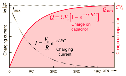
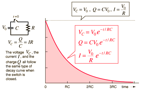
ps just keep in mined that the discharge chars is just the opposite.


http://hyperphysics.phy-astr.gsu.edu/hbase/electric/capdis.html#c1
http://hyperphysics.phy-astr.gsu.edu/hbase/electric/capchg.html#c2

one dog... if you can make reference's of where the chars/data is from that would be grate lol  :) thanks!

Matt Watts

RE: Let's build A "Popper" Noble Gas Engine AKA Ppap Engine.
« Reply #1509, on January 21st, 2013, 12:36 AM »Last edited on January 21st, 2013, 12:41 AM by Matt Watts
Quote from ~Russ/Rwg42985 on January 21st, 2013, 12:24 AM
but. if we use a short timed pulse we can stay in the upper ranges of the chart and that's what i'm thinking needs to be done... this will give us high short high energy pulses. we just need to see how it reacts to make it work and keep it balanced.

its possible to use a power resister or inductor to liniment the current draw but keep the energy in the range we need to make the reaction work...

~Russ

ps just keep in mined that the discharge chars is just the opposite.

http://hyperphysics.phy-astr.gsu.edu/hbase/electric/imgele/capdis.gif
From what I can tell so far, we have no control over the discharge rate, but it's fast so that gives us most of the cycle to begin recharging.  I use a halogen lamp bulb at whatever rating the transformer is, connected in series on the primary side.  So far I haven't burned anything up except for everything that is electrostaticly sensitive setting in the vicinity of the plasma arc.

And I love the smell of NOx and ozone in the morning.  hehe  :D
Quote from ~Russ/Rwg42985 on January 21st, 2013, 12:24 AM
one dog... if you can make reference's of where the chars/data is from that would be grate lol  :) thanks!
I'm old Russ, I can't race you.  All I can do is have the cops waiting for you at the finish line.   :)

~Russ

RE: Let's build A "Popper" Noble Gas Engine AKA Ppap Engine.
« Reply #1510, on January 21st, 2013, 01:02 AM »Last edited on January 21st, 2013, 01:03 AM by ~Russ/Rwg42985
Quote from Dog-One on January 21st, 2013, 12:36 AM
Quote from ~Russ/Rwg42985 on January 21st, 2013, 12:24 AM
but. if we use a short timed pulse we can stay in the upper ranges of the chart and that's what i'm thinking needs to be done... this will give us high short high energy pulses. we just need to see how it reacts to make it work and keep it balanced.

its possible to use a power resister or inductor to liniment the current draw but keep the energy in the range we need to make the reaction work...

~Russ

ps just keep in mined that the discharge chars is just the opposite.

http://hyperphysics.phy-astr.gsu.edu/hbase/electric/imgele/capdis.gif
From what I can tell so far, we have no control over the discharge rate, but it's fast so that gives us most of the cycle to begin recharging.  I use a halogen lamp bulb at whatever rating the transformer is, connected in series on the primary side.  So far I haven't burned anything up except for everything that is electrostaticly sensitive setting in the vicinity of the plasma arc.

And I love the smell of NOx and ozone in the morning.  hehe  :D
Quote from ~Russ/Rwg42985 on January 21st, 2013, 12:24 AM
one dog... if you can make reference's of where the chars/data is from that would be grate lol  :) thanks!
I'm old Russ, I can't race you.  All I can do is have the cops waiting for you at the finish line.   :)
controlling the rate suggested in this post: http://open-source-energy.org/?tid=659&pid=12151#pid12151

reference... i got in trouble once ( more than once) for peeps not posting reference links... :) ( this was before you were here)

~Russ

element 119

RE: Let's build A "Popper" Noble Gas Engine AKA Ppap Engine.
« Reply #1511, on January 21st, 2013, 01:40 PM »
Quote from Axil on January 20th, 2013, 08:55 PM
Quote from element 119 on January 20th, 2013, 08:37 PM
Quote
So sorry Axil if I mis-understood your position on this
This is my position. If it is based on faulty information, please let me know.

I picked 500 joules because that is the energy level that Bob Rohner is using.

Russ is using that level also since he is following the lead of BR.

Where did BR get this energy level from? Obviously not from the Papp engine patent description.

Russ wants to use even high energy levels and voltages. You are saying this idea is a mistake and poor engineering?

I am interested in minimizing input energy though innovative design.

If anybody succeeds in duplicating what Russ and BR are doing with less energy input, we all want to know how you are doing it.
Sorry Axil I didn’t make myself clear. You wrote this.

------------------------------------------------------------------------
“For example, Papp put his capacitors very close to the point of spark discharge; close to the cylinder.

Electric power flows at a finite speed; one nanosecond per foot based on the voltage. If the length of the feed wire is minimized, then the plasmoid might form faster. Experimentation will tell.”
------------------------------------------------------------------------------


But from what I can tell Papp did not use a capacitor discharge system like Russ. That is what I meant about you being wrong. But I agree with your thinking on making a system that uses the least amount of input energy.
It could be that Papp engine collected excess voltage from one cylinder for use on the other cylinder but I’m not sure it is known what that voltage range was or if it was reduced down to 24 volts.

element 119

k c dias

RE: Let's build A "Popper" Noble Gas Engine AKA Ppap Engine.
« Reply #1512, on January 21st, 2013, 01:48 PM »
IMHO sounds like you guys are building a 'tungsten vapor engine'.  Surely, converting a tungsten solid to a tungsten vapor will move a piston, but I'm not so sure it will be very efficient.  Proceed with caution, you will be dealing with some dangerous power!

Remember what Papp said (to Feynman) "Power to run engine does not come from wall socket".  

FaradayEZ

RE: Let's build A "Popper" Noble Gas Engine AKA Ppap Engine.
« Reply #1513, on January 22nd, 2013, 02:46 AM »Last edited on January 22nd, 2013, 02:55 AM by FaradayEZ
Quote from Axil on January 20th, 2013, 07:52 PM
Quarter Shrinker


http://intellectualventureslab.com/?p=71

this is something Russ can do with his capacitor bank. This demonstrates how much instantaneous power can be produced through capacitor discharge.
Quantatative easing is doing this also to the pensioners, and worldwide this bubble is inflated. See keiserreports on RT. Invest in Zilver.
Quote from ~Russ/Rwg42985 on January 20th, 2013, 07:41 PM
Quote from FaradayEZ on January 20th, 2013, 12:23 PM
Don't want to dempen the parade's here, but i'm still waiting for the / some real tests to begin. We have three people with poppers and we have a lot of making sense test already gathered.

I thought we really wanted to know how the papp engine functions, or do we first want to make a fluxcapacitor to get something going?

And can't we do both?
time time time... we will get there.. There was about 20 more things to add the the list and its all floating around in my head so I'm trying to figure out whats highest priority and how to achieve that. I'm just now getting to finish the controlling circuit... ( finishing drawings and finding the correct components...)


we will get there EZ with life comes patients. :)

believe me I'm itching to get back on it but family comes first...

ok enjoy. ~Russ
I know, time etc. But it would be so nice if we can stripe some questions away. If we have some hard answers where we can build new bloks on.

So let anyone with a popper not hesitate to do some work on the popper-test sheets. Maybe now they think their exclusive for you to use? Which shouldn't be thought, its a group effort.


FaradayEZ

RE: Let's build A "Popper" Noble Gas Engine AKA Ppap Engine.
« Reply #1514, on January 22nd, 2013, 05:49 AM »Last edited on January 22nd, 2013, 06:02 AM by FaradayEZ
Quote from ~Russ/Rwg42985 on January 20th, 2013, 09:02 PM
that's ( drum roll please) 1.5J that's right 1.5 joules

so there are no other caps anywhere? hummm.

my conclusions.
if we use the "buckets" and the Low voltage, magnetic excitement, RF, and High voltage.  we may only need a tinny trier to set it off... 1.5J may be enough...

although i did read that the caps are always attached to the anode and cathode... so there constantly "discharging" on the anode and cathode.

there is not a cap discharge type circuit that we know of...
The discharge is done by the piston with its bolt getting into the right place. The discharge time seems to be until the piston is far enough on its way to break contact. After that the caps and plugs are recharging, like constantly.
Quote
"(During the TDC to BDC portion of the cycle, these capacitors are charged and/or discharged by the same currents as are supplied to the anode and cathode since they are directly connected thereto.)"
Quote
so the other energys are need to make the reaction happen... (HV, magnetic excitement, RF) but with out the other source of radiation energy... we may never reach the required power input levels to make this anymore better than the average electric motor...
Why do we think that the radiation has so much influence? If it really was a significant source of ionization, of making electrons, then we would have used it already more often as a battery, no? If we would calculate how much it free's up
electronwise, then we probably will find only a small amount...electrically


Quote from element 119 on January 21st, 2013, 01:40 PM
But from what I can tell Papp did not use a capacitor discharge system like Russ. That is what I meant about you being wrong. But I agree with your thinking on making a system that uses the least amount of input energy.
It could be that Papp engine collected excess voltage from one cylinder for use on the other cylinder but I’m not sure it is known what that voltage range was or if it was reduced down to 24 volts.

element 119
From Sabottori words it was like a whole bunch of ampere's, not much voltage. And that they could use the voltage but not the ampere's...strange...

Why not put the amps through a transformer then to gain more volts?

jabowery

RE: Let's build A "Popper" Noble Gas Engine AKA Ppap Engine.
« Reply #1515, on January 22nd, 2013, 11:18 AM »Last edited on January 22nd, 2013, 11:27 AM by jabowery
Quote from Dog-One on January 20th, 2013, 09:28 PM
Russ, the part that kicked my butt was recharge time.  I can spend 20 minutes and make a plasma arc that blow your windows out, but doing this consistently every 33ms is a bearcat.
The way to get fast recharge is the same way to get fast discharge:

Use magnetic energy in coils rather than electrical energy in capacitors.

Capacitors can be used to bootstrap.

PS:  I came to this conclusion while trying to figure out why Paul Koloc's attempt at a ball lightning machine wasn't producing the correct current vs time profile.  I altered the SPICE model to use induction rather than capacitance and BOOM, the plots matched empirical measurement of lightning perfectly.

Jeff Nading

RE: Let's build A "Popper" Noble Gas Engine AKA Ppap Engine.
« Reply #1516, on January 22nd, 2013, 11:35 AM »
Quote from jabowery on January 22nd, 2013, 11:18 AM
Quote from Dog-One on January 20th, 2013, 09:28 PM
Russ, the part that kicked my butt was recharge time.  I can spend 20 minutes and make a plasma arc that blow your windows out, but doing this consistently every 33ms is a bearcat.
The way to get fast recharge is the same way to get fast discharge:

Use magnetic energy in coils rather than electrical energy in capacitors.

Capacitors can be used to bootstrap.

PS:  I came to this conclusion while trying to figure out why Paul Koloc's attempt at a ball lightning machine wasn't producing the correct current vs time profile.  I altered the SPICE model to use induction rather than capacitance and BOOM, the plots matched empirical measurement of lightning perfectly.
Could you post some photos and of the transformer or how this was done? Thanks.:D

Axil

RE: Let's build A "Popper" Noble Gas Engine AKA Ppap Engine.
« Reply #1517, on January 22nd, 2013, 12:27 PM »Last edited on January 22nd, 2013, 12:45 PM by Axil
The key component that will determine how well a pulsed power system does its function is the capacitor. If the capacitor is selected correctly, its performance will be consistent with the job it is required to perform, and then the job will succeed.
Let us look into the way a capacitor works. A capacitor is like a tank of water. When such a take is full, the pressure of the water discharged from its base is high.

But as the tank empties, the pressure of the water decreases in proportion to the height of water in the tank.

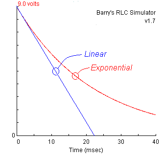
The rate of discharge is not linear because like water height in a tank the current drops as the voltage drains away. This means that a capacitor discharges at a progressively slower rate over time.

An ideal capacitor will never completely discharge because the charge will gradually approach zero volts but never quite reach it.

Both the current and the voltage of a discharging capacitor decay exponentially.

When you do the math for a capacitor discharge, you get an exponential decay curve: V(t) = V0 e(exp)-t / RC
This curve starts at the initial capacitor voltage (V0), and diminishes quickly at first. As time goes by, the slope of the curve becomes less and less while the voltage approaches but does not reach zero.

However, for all practical purposes the capacitor might as well be empty by the time 99% of the initial charge has escaped.

Shown below is a comparison between a linear and exponential decay for this circuit. The exponential curve is a screen shot taken from the RLC Simulator applet.


The rate of removal of charge is proportional to the amount of charge remaining.

Because capacitors discharge exponentially, their charge falls away in a similar way to radioactive material decay. In radioactivity you have a half-life, in capacitance you have a 'time constant'.

If we want the capacitor to charge fast and discharge fast, we need to keep the fullness of the capacitor high to keep the voltage provided by the capacitor high.

A capacitor with a high voltage rating will charge fast and discharge fast when its fullness level is high.

The voltage rating of capacitors used in pulse power systems are high indeed, with a value over 100kV.

The voltage rating of a high capacity capacitor over 1 MeV is best.

Strangely enough, pure water is an ideal dielectric for such a capacitor because the fast relaxation time of the water molecule gives an even faster output pulse (tens of nanoseconds?).

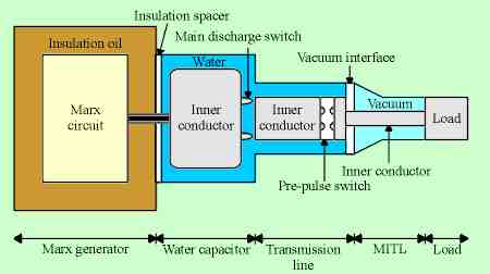
Discharge from such a capacitor can then be fed into a pulse forming and impedance matching network before coupling to the load. Here is a representative illustration from Kumamoto University:


The Marx generator provides for high voltage charging, with its long chain of spark gaps and simply its overall size, has a fairly high inductance (a few microheneries ), which is difficult to reduce because of the extremely high voltage gradients. A properly constructed peaking capacitor, along with another spark gap switch, can reduce this to a few nanoheneries, which in turn enables rise times of only a few nanoseconds. Some applications, such as flash radiography of exploding materials (as in atomic weapons research), require these high power, ultra short pulses.

What the Papp engine really is.

The first Papp engine design was a water capacitor. It used water as a dielectric to store charge at a high voltage.

Like the Marx generator in our example, The 40,000 volt spark discharge that the auto coils provide is just a means to top off the stored charge contained in the cylinder so that this Papp capacitor would discharge to the other mated cylinder in nanoseconds and at high voltage.

The Papp cylinder is a pulsed power system which produces high voltage discharge in nanoseconds.

We have been calling this capacitive discharge the feedback current.

For the Papp engine to work, the cylinders must be paired so that each Papp “capacitor” discharges at a very high voltage to the mated cylinder in a ping pong mode.

The Popper is an incomplete system. It will not work because it does not have a paired cylinder to receive and reflect the high voltage discharge from another Papp cylinder.

In the second Papp design, the noble gas mix is an ideal dielectric medium to store the capacitive discharge.

The Papp cylinder is the capacitor that creates the explosive spark discharge in the mated cylinder.

This is a repetitive explosive process as charge ping-pongs between the mated cylinders.

The over unity charge accumulation will eventually explode one of the cylinders if the feedback current is not moderated using charge dissipation.

As we saw in this video at 10:16, a high voltage capacitor will explode when charged by a feedback current from a noble gas filled cylinder.


https://www.youtube.com/watch?v=EXD3ZFkXyw8

What happened in the Feynman demo now makes sense.

When the charge dissipation function of Papp control box was removed from the Papp process in the Feynman demo, one of the mated cylinders did explode.

In this behavior of capacitors, lies the secret of the Papp engine.


Quote from jabowery on January 22nd, 2013, 11:18 AM
Quote from Dog-One on January 20th, 2013, 09:28 PM
Russ, the part that kicked my butt was recharge time.  I can spend 20 minutes and make a plasma arc that blow your windows out, but doing this consistently every 33ms is a bearcat.
The way to get fast recharge is the same way to get fast discharge:

Use magnetic energy in coils rather than electrical energy in capacitors.

Capacitors can be used to bootstrap.

PS:  I came to this conclusion while trying to figure out why Paul Koloc's attempt at a ball lightning machine wasn't producing the correct current vs time profile.  I altered the SPICE model to use induction rather than capacitance and BOOM, the plots matched empirical measurement of lightning perfectly.
The storage of energy using capacitance is fundamental to the design of the Papp engine as explained in my last post.

Jeff Nading

RE: Let's build A "Popper" Noble Gas Engine AKA Ppap Engine.
« Reply #1518, on January 22nd, 2013, 02:22 PM »
Quote from Axil on January 22nd, 2013, 12:27 PM
The key component that will determine how well a pulsed power system does its function is the capacitor. If the capacitor is selected correctly, its performance will be consistent with the job it is required to perform, and then the job will succeed.
Let us look into the way a capacitor works. A capacitor is like a tank of water. When such a take is full, the pressure of the water discharged from its base is high.

But as the tank empties, the pressure of the water decreases in proportion to the height of water in the tank.

The rate of discharge is not linear because like water height in a tank the current drops as the voltage drains away. This means that a capacitor discharges at a progressively slower rate over time.

An ideal capacitor will never completely discharge because the charge will gradually approach zero volts but never quite reach it.

Both the current and the voltage of a discharging capacitor decay exponentially.

When you do the math for a capacitor discharge, you get an exponential decay curve: V(t) = V0 e(exp)-t / RC
This curve starts at the initial capacitor voltage (V0), and diminishes quickly at first. As time goes by, the slope of the curve becomes less and less while the voltage approaches but does not reach zero.

However, for all practical purposes the capacitor might as well be empty by the time 99% of the initial charge has escaped.

Shown below is a comparison between a linear and exponential decay for this circuit. The exponential curve is a screen shot taken from the RLC Simulator applet.


The rate of removal of charge is proportional to the amount of charge remaining.

Because capacitors discharge exponentially, their charge falls away in a similar way to radioactive material decay. In radioactivity you have a half-life, in capacitance you have a 'time constant'.

If we want the capacitor to charge fast and discharge fast, we need to keep the fullness of the capacitor high to keep the voltage provided by the capacitor high.

A capacitor with a high voltage rating will charge fast and discharge fast when its fullness level is high.

The voltage rating of capacitors used in pulse power systems are high indeed, with a value over 100kV.

The voltage rating of a high capacity capacitor over 1 MeV is best.

Strangely enough, pure water is an ideal dielectric for such a capacitor because the fast relaxation time of the water molecule gives an even faster output pulse (tens of nanoseconds?).

Discharge from such a capacitor can then be fed into a pulse forming and impedance matching network before coupling to the load. Here is a representative illustration from Kumamoto University:


The Marx generator provides for high voltage charging, with its long chain of spark gaps and simply its overall size, has a fairly high inductance (a few microheneries ), which is difficult to reduce because of the extremely high voltage gradients. A properly constructed peaking capacitor, along with another spark gap switch, can reduce this to a few nanoheneries, which in turn enables rise times of only a few nanoseconds. Some applications, such as flash radiography of exploding materials (as in atomic weapons research), require these high power, ultra short pulses.

What the Papp engine really is.

The first Papp engine design was a water capacitor. It used water as a dielectric to store charge at a high voltage.

Like the Marx generator in our example, The 40,000 volt spark discharge that the auto coils provide is just a means to top off the stored charge contained in the cylinder so that this Papp capacitor would discharge to the other mated cylinder in nanoseconds and at high voltage.

The Papp cylinder is a pulsed power system which produces high voltage discharge in nanoseconds.

We have been calling this capacitive discharge the feedback current.

For the Papp engine to work, the cylinders must be paired so that each Papp “capacitor” discharges at a very high voltage to the mated cylinder in a ping pong mode.

The Popper is an incomplete system. It will not work because it does not have a paired cylinder to receive and reflect the high voltage discharge from another Papp cylinder.

In the second Papp design, the noble gas mix is an ideal dielectric medium to store the capacitive discharge.

The Papp cylinder is the capacitor that creates the explosive spark discharge in the mated cylinder.

This is a repetitive explosive process as charge ping-pongs between the mated cylinders.

The over unity charge accumulation will eventually explode one of the cylinders if the feedback current is not moderated using charge dissipation.

As we saw in this video at 10:16, a high voltage capacitor will explode when charged by a feedback current from a noble gas filled cylinder.


https://www.youtube.com/watch?v=EXD3ZFkXyw8

What happened in the Feynman demo now makes sense.

When the charge dissipation function of Papp control box was removed from the Papp process in the Feynman demo, one of the mated cylinders did explode.

In this behavior of capacitors, lies the secret of the Papp engine.


Quote from jabowery on January 22nd, 2013, 11:18 AM
Quote from Dog-One on January 20th, 2013, 09:28 PM
Russ, the part that kicked my butt was recharge time.  I can spend 20 minutes and make a plasma arc that blow your windows out, but doing this consistently every 33ms is a bearcat.
The way to get fast recharge is the same way to get fast discharge:

Use magnetic energy in coils rather than electrical energy in capacitors.

Capacitors can be used to bootstrap.

PS:  I came to this conclusion while trying to figure out why Paul Koloc's attempt at a ball lightning machine wasn't producing the correct current vs time profile.  I altered the SPICE model to use induction rather than capacitance and BOOM, the plots matched empirical measurement of lightning perfectly.
The storage of energy using capacitance is fundamental to the design of the Papp engine as explained in my last post.
I think jabowery might have something here, magnetic inductance is one thing Tesla used.

Jed

RE: Let's build A "Popper" Noble Gas Engine AKA Ppap Engine.
« Reply #1519, on January 22nd, 2013, 03:19 PM »
Jeff Nading Wrote:
Could you post .....
Background: You have a 1.3 m long copper wire. You want to make an N-turn current loop that generates a 1.6 mT magnetic field at the center when the current is 1.5 A. You must use the entire wire. What will be the diameter of your coil? Let u = permeability constant in air
u = 4 * pi * 10E-7
B = u I N / (2 R) field at center of coil of N turns
N = L / (2 * pi * R) number of turns made from length of wire L
4 R^2 = u I L / (B * pi) substituting for N in the first equation
D = (u I L /B * pi)^1/2 since D = 2 * R
D = (4 * 10E-7 * 1.5 * 1.3/ 1.6 *10^-3)^1/2 = 0.0698212..
http://hyperphysics.phy-astr.gsu.edu/hbase/electric/indeng.html
http://hyperphysics.phy-astr.gsu.edu/hbase/electric/engfie.html#c1

Picked up this (Thanks Russ) http://i.ebayimg.com/t/Acme-Transformer-750VA-Primary-220v-480v-Secondary-110v-120v-TA-1-81216-750VA-/00/s/MTAwMFgxMDAw/$(KGrHqR,!jIFCw7koolNBQzMRWc03!~~60_58.JPG
Acquired this as suggested in a post here:  http://classified.ndntp.com/Images/2011/12000ufa.JPG
Will construct a bridge with: http://www.ebay.com/itm/40-amp-Stud-Mount-Rectifier-Diode-400V-NTE5991-Wind-Solar-PWM-HHO-RV-/181064458666?pt=LH_DefaultDomain_0&hash=item2a284861aa

Jed

Matt Watts

RE: Let's build A "Popper" Noble Gas Engine AKA Ppap Engine.
« Reply #1520, on January 22nd, 2013, 04:57 PM »
Quote from Jeff Nading on January 22nd, 2013, 02:22 PM
I think jabowery might have something here, magnetic inductance is one thing Tesla used.
So we should be using this:
http://hyperphysics.phy-astr.gsu.edu/hbase/electric/indeng.html

instead of this:
http://hyperphysics.phy-astr.gsu.edu/hbase/electric/capchg.html#c2

Figures given two choices I would pick the wrong one.  Errr...

element 119

RE: Let's build A "Popper" Noble Gas Engine AKA Ppap Engine.
« Reply #1521, on January 22nd, 2013, 05:48 PM »
Quote from Axil on January 22nd, 2013, 12:27 PM
The Papp cylinder is a pulsed power system which produces high voltage discharge in nanoseconds.

We have been calling this capacitive discharge the feedback current.

For the Papp engine to work, the cylinders must be paired so that each Papp “capacitor” discharges at a very high voltage to the mated cylinder in a ping pong mode.

The Popper is an incomplete system. It will not work because it does not have a paired cylinder to receive and reflect the high voltage discharge from another Papp cylinder.

In the second Papp design, the noble gas mix is an ideal dielectric medium to store the capacitive discharge.

The Papp cylinder is the capacitor that creates the explosive spark discharge in the mated cylinder.

This is a repetitive explosive process as charge ping-pongs between the mated cylinders.

The over unity charge accumulation will eventually explode one of the cylinders if the feedback current is not moderated using charge dissipation.
Good thinking Axil and I have some questions pertaining to the Papp system.

Staring event: cylinder 1 is at TDC and cylinder 2 is at BDC therefore something must happen to drive cylinder 1 to BDC and cylinder 2 to TDC.

There does not appear to be enough for this to happen with just 40 KV and 24 V DC on the electrodes.

But we do have a starter and this can mechanically drive cylinder 1 to BDC.

While this is happening then something must be occurring to charge up the N. gasses to a high potential to cause a high discharge in cylinder 2.

Can we assume (?) the gasses are stretched (?) from the starter moving the piston to BDC. So if the 40KV is on or pulsed (3 times ?) during this time is that where the gasses receive there capacitive charge?

Next turning to the popper like Bob and Russ have.

Even though turned upside down the popper piston is at TDC, vacuum is applied and gasses installed. So for a good experiment if the piston was mechanically pulled to BDC and then an HV is applied would it charge up the N. gasses then maybe transferred to capacitors ready for next pop?

The reason I am asking is Russ did not as far as I know see any recharging of the capacitors after firing the popper. Factors that could have stopped this from happening is the HV was not left on till BDC was reached or the gas charge needs to be rectified to DC to recharge the capacitors.


Matt Watts

RE: Let's build A "Popper" Noble Gas Engine AKA Ppap Engine.
« Reply #1522, on January 22nd, 2013, 06:53 PM »
Quote from element 119 on January 22nd, 2013, 05:48 PM
Good thinking Axil and I have some questions pertaining to the Papp system.

Staring event: cylinder 1 is at TDC and cylinder 2 is at BDC therefore something must happen to drive cylinder 1 to BDC and cylinder 2 to TDC.

There does not appear to be enough for this to happen with just 40 KV and 24 V DC on the electrodes.

But we do have a starter and this can mechanically drive cylinder 1 to BDC.

While this is happening then something must be occurring to charge up the N. gasses to a high potential to cause a high discharge in cylinder 2.

Can we assume (?) the gasses are stretched (?) from the starter moving the piston to BDC. So if the 40KV is on or pulsed (3 times ?) during this time is that where the gasses receive there capacitive charge?

Next turning to the popper like Bob and Russ have.

Even though turned upside down the popper piston is at TDC, vacuum is applied and gasses installed. So for a good experiment if the piston was mechanically pulled to BDC and then an HV is applied would it charge up the N. gasses then maybe transferred to capacitors ready for next pop?

The reason I am asking is Russ did not as far as I know see any recharging of the capacitors after firing the popper. Factors that could have stopped this from happening is the HV was not left on till BDC was reached or the gas charge needs to be rectified to DC to recharge the capacitors.
Charging, charging...   Where have I seen that before.  Oh yeah, Konehead and his technique for shorting coils at peaks.
http://peswiki.com/index.php/OS:Doug_Konzen_%28Konehead%29_on_Self-Looped_Generators
Maybe something there if I could see where the magnetic field is coming from.

One of those dis-assembly videos of the Papp motor showed a fixed piston with a moving cylinder.  Is there something about that design that would create a magnetic field?

Axil

RE: Let's build A "Popper" Noble Gas Engine AKA Ppap Engine.
« Reply #1523, on January 22nd, 2013, 06:54 PM »Last edited on January 22nd, 2013, 07:03 PM by Axil
Quote from element 119 on January 22nd, 2013, 05:48 PM
Quote from Axil on January 22nd, 2013, 12:27 PM
The Papp cylinder is a pulsed power system which produces high voltage discharge in nanoseconds.

We have been calling this capacitive discharge the feedback current.

For the Papp engine to work, the cylinders must be paired so that each Papp “capacitor” discharges at a very high voltage to the mated cylinder in a ping pong mode.

The Popper is an incomplete system. It will not work because it does not have a paired cylinder to receive and reflect the high voltage discharge from another Papp cylinder.

In the second Papp design, the noble gas mix is an ideal dielectric medium to store the capacitive discharge.

The Papp cylinder is the capacitor that creates the explosive spark discharge in the mated cylinder.

This is a repetitive explosive process as charge ping-pongs between the mated cylinders.

The over unity charge accumulation will eventually explode one of the cylinders if the feedback current is not moderated using charge dissipation.
Good thinking Axil and I have some questions pertaining to the Papp system.

Staring event: cylinder 1 is at TDC and cylinder 2 is at BDC therefore something must happen to drive cylinder 1 to BDC and cylinder 2 to TDC.

There does not appear to be enough for this to happen with just 40 KV and 24 V DC on the electrodes.

But we do have a starter and this can mechanically drive cylinder 1 to BDC.

While this is happening then something must be occurring to charge up the N. gasses to a high potential to cause a high discharge in cylinder 2.

Can we assume (?) the gasses are stretched (?) from the starter moving the piston to BDC. So if the 40KV is on or pulsed (3 times ?) during this time is that where the gasses receive there capacitive charge?

Next turning to the popper like Bob and Russ have.

Even though turned upside down the popper piston is at TDC, vacuum is applied and gasses installed. So for a good experiment if the piston was mechanically pulled to BDC and then an HV is applied would it charge up the N. gasses then maybe transferred to capacitors ready for next pop?

The reason I am asking is Russ did not as far as I know see any recharging of the capacitors after firing the popper. Factors that could have stopped this from happening is the HV was not left on till BDC was reached or the gas charge needs to be rectified to DC to recharge the capacitors.
Quote
Can we assume (?) the gasses are stretched (?) from the starter moving the piston to BDC. So if the 40KV is on or pulsed (3 times ?) during this time is that where the gasses receive there capacitive charge?
The starter will produce a vacuum in the noble gases. This vacuum will cool the gases and noble gas clustering will occur.

The 40kv spark discharge will fire a number of times while the starter is turning to charge the noble gases up to the point of full charge. When the gases in the cylinders are fully charged, the gases will discharge (feedback current) to feed the other mated cylinder.

The buckets will collect the feedback current and will rout it to the other cylinder; a ping pong discharge cycle will then begin.

The very important function of the Papp engine is to preserve, protect and collect the feedback current so that it can power the generation of the spark discharge in the other cylinder.

I speculate that the first spark discharge is the big one that produces the plasmoid which moves the piston.

What we have not figured out is how to preserve, protect and collect the feedback current for use in the mated cylinder.

If you remember, we have visualized  this noble gas charge when we saw the green florescent glow emanating from excited helium atoms after a spark discharge in past Popper tests produced by Russ.

The means to produce the 40kv spark is not important. What are critical is the preservation, protection and collection of the feedback current.

I suspect that the discharge current is feed directly to the electrodes in the other cylinder without interim storage in other storage capacitors. That is, the first cylinder in the mated pair is the pules capacitor for the second cylinder and vice versa.

Both Rohner brothers are not properly dealing with the feedback current and therein lays the root of their failure to produce a working Papp engine.


freethisone

RE: Let's build A "Popper" Noble Gas Engine AKA Ppap Engine.
« Reply #1524, on January 22nd, 2013, 07:00 PM »
Quote from Dog-One on January 22nd, 2013, 04:57 PM
Quote from Jeff Nading on January 22nd, 2013, 02:22 PM
I think jabowery might have something here, magnetic inductance is one thing Tesla used.
So we should be using this:
http://hyperphysics.phy-astr.gsu.edu/hbase/electric/indeng.html

instead of this:
http://hyperphysics.phy-astr.gsu.edu/hbase/electric/capchg.html#c2

Figures given two choices I would pick the wrong one.  Errr...
I am still with you here. lots of progress being made. good post Alix very good.
Dog one i just want to remind you of this thread. http://open-source-energy.org/?tid=838

If you want an inductor go Big! hehhe