Let's build A "Popper" Noble Gas Engine AKA Ppap Engine.

Axil

RE: Let's build A "Popper" Noble Gas Engine AKA Ppap Engine.
« Reply #775, on October 22nd, 2012, 12:49 AM »Last edited on October 22nd, 2012, 01:10 AM by Axil
Quote from FaradayEZ on October 22nd, 2012, 12:37 AM
Quote from Axil on October 21st, 2012, 11:09 PM
Dr. James Truchard President, CEO, and Cofounder of National Instruments is excited about LENR. If he is approached properly, Truchard may be persuaded to provide Russ with a free copy of LabView and associated test equipment to support Russ’s testing.

Let's talk about this.
Looks like a decent opportunity!
And maybe alongside the software usage, he can find and introduce some students of the university he has ties with to make a project on the popper?
For this university project to happen and to convince Truchard, Russ needs to stand up and present his beautifully formatted computer generated experimental results in front of the next LENR conference  to show all concerned that the Papp engine is the only way to go with regards to LENR.

symanuk

RE: Let's build A "Popper" Noble Gas Engine AKA Ppap Engine.
« Reply #776, on October 22nd, 2012, 01:07 AM »
I think you would struggle to prove that the Papp engine is the ONLY way to go with LENR - the LeClair Effect with cavitation has had years of deep scientific experimentation in this regard and has a lot more "integrity" for better or worse from a scientific standpoint.  Russ is definitely on to something - but is only at the start of the process to observe and measure exactly what it is.  I think they should get on board with helping to prove and measure with Russ, but to say it is the only way to go would be quite closed minded at this point in time is my opinion

Axil

RE: Let's build A "Popper" Noble Gas Engine AKA Ppap Engine.
« Reply #777, on October 22nd, 2012, 01:24 AM »Last edited on October 22nd, 2012, 01:39 AM by Axil
Quote from symanuk on October 22nd, 2012, 01:07 AM
I think you would struggle to prove that the Papp engine is the ONLY way to go with LENR - the LeClair Effect with cavitation has had years of deep scientific experimentation in this regard and has a lot more "integrity" for better or worse from a scientific standpoint.  Russ is definitely on to something - but is only at the start of the process to observe and measure exactly what it is.  I think they should get on board with helping to prove and measure with Russ, but to say it is the only way to go would be quite closed minded at this point in time is my opinion
My opinion is based on the following simple way of thinking.

LeClair can only produce a temperate rise in heating water of a just a few degrees. LeClair cannot generate electricity because cavatation cannot happen above 80C. If he can use molten salts for cavitation, this might change, but he has not even considered this option.

Any heat producing LENR reaction is restricted to under 40% thermodynamic efficiency at most with loads of expensive steam to electric power conversion equipment required.

On the other hand, the Papp engine will produce electric power directly at very high efficiency at 95% or more. You see, the papp engine does not produce heat.

Energy return on energy investment is unsurpassed for the Papp engine. In other words, it is cheap to build for the amount of energy that you can get out of it.


FaradayEZ

RE: Let's build A "Popper" Noble Gas Engine AKA Ppap Engine.
« Reply #778, on October 22nd, 2012, 05:21 AM »
Quote from Axil on October 22nd, 2012, 01:24 AM
Quote from symanuk on October 22nd, 2012, 01:07 AM
I think you would struggle to prove that the Papp engine is the ONLY way to go with LENR - the LeClair Effect with cavitation has had years of deep scientific experimentation in this regard and has a lot more "integrity" for better or worse from a scientific standpoint.  Russ is definitely on to something - but is only at the start of the process to observe and measure exactly what it is.  I think they should get on board with helping to prove and measure with Russ, but to say it is the only way to go would be quite closed minded at this point in time is my opinion
My opinion is based on the following simple way of thinking.

LeClair can only produce a temperate rise in heating water of a just a few degrees. LeClair cannot generate electricity because cavatation cannot happen above 80C. If he can use molten salts for cavitation, this might change, but he has not even considered this option.

Any heat producing LENR reaction is restricted to under 40% thermodynamic efficiency at most with loads of expensive steam to electric power conversion equipment required.

On the other hand, the Papp engine will produce electric power directly at very high efficiency at 95% or more. You see, the papp engine does not produce heat.

Energy return on energy investment is unsurpassed for the Papp engine. In other words, it is cheap to build for the amount of energy that you can get out of it.
We can always place bets later... Thing is that with all the video's on Papp etc. there is enough information to get some students interested in helping this Popper project to the next level. And also to already convince James Truchard of the interesting side's of this.

That Russ has a working table testmodel is ideal for them. Its what they grave for...

Just have to bring the parties together.

Next project...


k c dias

RE: Let's build A "Popper" Noble Gas Engine AKA Ppap Engine.
« Reply #779, on October 22nd, 2012, 11:27 AM »Last edited on October 22nd, 2012, 11:33 AM by k c dias
Quote from BobN on October 21st, 2012, 02:39 PM
The Photo interrupter will be good for control on velocity and position, but I'm not sure you will learn much about the gas activity. The flywheel sensor might be valuable to use in trying to characterize the plasma activity if its as sensitive as you mention. The piston is hollow so the gas may be doing different things than the piston. I thing its behavior in the cylinder should be characterized.  

Photo Interrupters have delays of about 3 microseconds. That needs to be factored in to any control usage.

Yes, it would work well for timing the spark, I was just saying that the magnetic detector may tell us a lot more about the gas behavior if we try and characterize the gas movement. The current in the gas can be characterized, a lot of information possible.
BobN,

Thanks!  The magnetic sensor has not been retired, its loose and connected to the scope.  As you have suggested, it has become a useful tool as a sniffer. :)  The delay can be factored into the controller, I have a variable 'DeadTime' that can be defined for each section of the controller, for example, the 'MainMCU', that addresses the flywheel sensor input, and then also for each output stage (separate MCU's, and definable DeadTimes), for the HV ignition coils, the RF switching, and the cylinder coils (upper and lower)  The timing can be set up very precisely, as long as the input pulses are clean.  

Even the photo interrupter (0-5 TTL output) was susceptible to some small spikes that were picked up from the coils firing.  I set up a comparator buffer stage with a adjustable reference that I can set at 2.5 to 3V.  This has helped tremendously to get the signal above the noise floor.

The real, if-I-had-to-do-it-over-again fix would be as JR has done  That is to do all of the switching close to the device being switched, thus keeping the wires (antennas) as short as possible.  Keep only the controller core on the central board, and keep this close (short wire run) to the input timing sensor.

I have been hesitant to release any of the controller details until I have the engine running.  But if there are others that would like to get going on their own engine testing, then perhaps I should release a 'beta' version.  Any comments??

kcd
Quote from Axil on October 21st, 2012, 03:15 PM
In summary, the only way to find out the details of how the Papp engine really works is to do vast numbers of experiments.

For this reason, I am hoping that the members of our forum who are energetic enough to do these experiments will not tire or lose interest and will share their results no matter what these experiments show.
Axil,

Thank you again - you are a great asset to this forum!  There is much to do!

kcd


Badger

RE: Let's build A "Popper" Noble Gas Engine AKA Ppap Engine.
« Reply #780, on October 22nd, 2012, 11:59 AM »
Quote from k c dias on October 22nd, 2012, 11:27 AM
I have been hesitant to release any of the controller details until I have the engine running.  But if there are others that would like to get going on their own engine testing, then perhaps I should release a 'beta' version.  Any comments??

kcd
kcd,
I'd love to hear some details of how you're doing your controller! Are you putting together any type of material list or "to do" conversion?  I think more experimenters could get on board if some of the parts were easier to get, like the gas or spark plugs... maybe a preprogrammed micro processor...

k c dias

RE: Let's build A "Popper" Noble Gas Engine AKA Ppap Engine.
« Reply #781, on October 22nd, 2012, 01:23 PM »
Quote from Badger on October 22nd, 2012, 11:59 AM
Quote from k c dias on October 22nd, 2012, 11:27 AM
I have been hesitant to release any of the controller details until I have the engine running.  But if there are others that would like to get going on their own engine testing, then perhaps I should release a 'beta' version.  Any comments??

kcd
kcd,
I'd love to hear some details of how you're doing your controller! Are you putting together any type of material list or "to do" conversion?  I think more experimenters could get on board if some of the parts were easier to get, like the gas or spark plugs... maybe a preprogrammed micro processor...
Badger,

Thanks for your interest :)  I did describe the controller in some detail in this post:
http://open-source-energy.org/?tid=659&pid=7570#pid7570

A few things have changed, like swapping the magnetic sensor for the photo interrupter, but the basic configuration is unchanged.

Pre-programmed chips may sound like a good idea at first, but, folks will soon want to make changes on there own to the timing, or whatever.  I have tried to write the code with lots of comments, and I use several 'call' instructions to run subroutines that do most of the heavy lifting, the actual code that times the event uses about a 1/2 of a page of lines, and that's it.  Then there is also a lookup table or two at the end of the listing to read the timing and duration values as a function of shaft speed.  I have an Excel sheet that the user can input the timing numbers in degrees, and it calculates the numbers needed to enter into the lookup table.

I use a PICkit2 programmer.  The starter kit is $50.  There is now a PICkit3, I guess, a newer version.  The programmer connects to the USB port and writes the .HEX file to the chip.  The MPELAB IDE program (I'm using 7.20, probably old) is used to write and edit the .asm files, which, in turn assembles the .HEX files.  There is also a MPLAB SIM debugger tool that you can start to step through or run your program, set breakpoints, observe file registers, etc.

I hope this info helps.  I will work towards putting together a beta version to release.

kcd

BobN

RE: Let's build A "Popper" Noble Gas Engine AKA Ppap Engine.
« Reply #782, on October 22nd, 2012, 02:08 PM »
Quote from k c dias on October 22nd, 2012, 01:23 PM
Quote from Badger on October 22nd, 2012, 11:59 AM
Quote from k c dias on October 22nd, 2012, 11:27 AM
I have been hesitant to release any of the controller details until I have the engine running.  But if there are others that would like to get going on their own engine testing, then perhaps I should release a 'beta' version.  Any comments??

kcd
kcd,
I'd love to hear some details of how you're doing your controller! Are you putting together any type of material list or "to do" conversion?  I think more experimenters could get on board if some of the parts were easier to get, like the gas or spark plugs... maybe a preprogrammed micro processor...
Badger,

Thanks for your interest :)  I did describe the controller in some detail in this post:
http://open-source-energy.org/?tid=659&pid=7570#pid7570

A few things have changed, like swapping the magnetic sensor for the photo interrupter, but the basic configuration is unchanged.

Pre-programmed chips may sound like a good idea at first, but, folks will soon want to make changes on there own to the timing, or whatever.  I have tried to write the code with lots of comments, and I use several 'call' instructions to run subroutines that do most of the heavy lifting, the actual code that times the event uses about a 1/2 of a page of lines, and that's it.  Then there is also a lookup table or two at the end of the listing to read the timing and duration values as a function of shaft speed.  I have an Excel sheet that the user can input the timing numbers in degrees, and it calculates the numbers needed to enter into the lookup table.

I use a PICkit2 programmer.  The starter kit is $50.  There is now a PICkit3, I guess, a newer version.  The programmer connects to the USB port and writes the .HEX file to the chip.  The MPELAB IDE program (I'm using 7.20, probably old) is used to write and edit the .asm files, which, in turn assembles the .HEX files.  There is also a MPLAB SIM debugger tool that you can start to step through or run your program, set breakpoints, observe file registers, etc.

I hope this info helps.  I will work towards putting together a beta version to release.

kcd
Good input on your controller. Right now I'm playing with different ways to build the controller. Your selection of the PIC is good, functional and low cost. Originally when I threw out the Raspberry it wasn't the best idea for quick adjustments to development, so for prototyping your choice is great.
Any special precautions or approaches for isolating the the high voltage sources from the logic. I suspect some real care needs to be taken so things are reliable.

Interesting to note that your getting IR hits from the cylinder. May need to be real selective in positioning and shielding sensors.

Thanks for sharing your work.

BobN

RussLinzmeier

RE: Let's build A "Popper" Noble Gas Engine AKA Ppap Engine.
« Reply #783, on October 22nd, 2012, 09:40 PM »Last edited on October 23rd, 2012, 06:17 AM by Jeff Nading
For what its worth , I found a video that might explain how the power is created to activate Russ Gries' popper when run on hydrogen . The video is   The Inside of Atomic Hydrogen Arc Welding ,Part 1 - 1943.

https://www.youtube.com/watch?v=uZwYMyHlWXk
  The process [ invented by Langmuir in the early 1900s ] has 3 elements to it . If you watch the video you'll notice a large billowing flame thats created from some of the hydrogen that gets burned up in the open air . This creates minimal heat but shields the weld . There is a low power A C  arc that is part of the process that doesn't penetrate the work piece and in no way has the power to create the energy that melts the metal and then there is the atomic hydrogen process that taps the zero point energy and puts the process into overunity .  The molecular hydrogen is changed to atomic hydrogen when blown thru the A C arc and recombines back to its molecular state when it contacts the work piece . More energy is released when the atoms recombine to form molecules than is required to take take the molecules apart .  If anyone disagrees that this process isn't overunity then create a 30 amp A C electric arc between 2 electrodes and see if it will melt 1/8 inch steel placed under it but just barely contacting the surface as the arc flows from one electrode to the other . Regular arc welding uses more power and flows the current thru the work piece . Is there any other arc welding that doesn't require a heavy cable to be clamped to the work piece so the energy of the welder isn't forced thru the torch to the work piece ?  

Badger

RE: Let's build A "Popper" Noble Gas Engine AKA Ppap Engine.
« Reply #784, on October 23rd, 2012, 06:09 AM »
Thanks for the info kcd, I knew you had a previous post on your controller, but I had trouble finding it yesterday.  Excuse my ignorance on MCUs, but could an Arduino or netduino (same?) perform the same functions?  Is it more for the separation of MCUs that you prefer the PIC or more because it's something you're familiar with?

k c dias

RE: Let's build A "Popper" Noble Gas Engine AKA Ppap Engine.
« Reply #785, on October 23rd, 2012, 12:42 PM »
Quote from BobN on October 22nd, 2012, 02:08 PM
Any special precautions or approaches for isolating the the high voltage sources from the logic. I suspect some real care needs to be taken so things are reliable.

Thanks for sharing your work.

BobN
Have a google at this part number: ISL9V3040P3.  These are basically 400V, 21A IGBT's for dummies - 5V logic level gate drive. :)  Send your TTL output through a 1k resistor to the gate input - dat's it, its that easy.  

Below is a photo of the controller.  On the right are the four ISL9V3040P3's for driving the coils (one for each of the three ignition coils, and the forth drives a speaker - a useful tool for detecting misfires).  That right side of the board will likely be cut off of the main board and relocated next to the ignition coils, the 1k resistors will remain on the controller board, and a ribbon cable used for interconnection.  As you can see, that is how I have handled the RF and top cylinder coil switching.
Quote from Badger on October 23rd, 2012, 06:09 AM
Thanks for the info kcd, I knew you had a previous post on your controller, but I had trouble finding it yesterday.  Excuse my ignorance on MCUs, but could an Arduino or netduino (same?) perform the same functions?  Is it more for the separation of MCUs that you prefer the PIC or more because it's something you're familiar with?
Sorry, I'm just not an Atmel guy.  Fortunately, I am right handed, because back in 3rd grade when I tried to write with my left hand, the teacher swiftly swatted it with a ruler.  Later in life, when I picked up the PIC instead of the Atmel, she wasn't there to swat my hand:( So its just PIC 4me.

Have a look at the controller board picture.  8 pins - that's all.  A 555timer chip is more complex to get going than these little puppies are.:D

kcd

simonderricutt

RE: Let's build A "Popper" Noble Gas Engine AKA Ppap Engine.
« Reply #786, on October 23rd, 2012, 02:22 PM »
k c dias - You've done a good job, but if you want to make a nice etched copper board you might try Tom Gootee's method at http://fullnet.com/~tomg/gooteepc.htm which works well. Use some paper towel as a pad under and over the board to provide a bit better pressure-transference when ironing, and experiment a bit before you try etching. It'll handle 10 thou track and gap. Hydrochloric acid and Hydrogen Peroxide makes a good cheap etch that is less problematical than Ferric Chloride. I've had good results, and the custom-made board is smaller, neater and you can work out the delays easier if it's high-speed. I like PICs, too.... If you etch the board you could use the little SOT-23-sized SMD ones. You can also iron-on a silk-screen to identify where the parts go.

Even with a 5V gate drive, it can be a good idea to use a FET driver chip to get faster rise and fall times of the output. Depends just how fast you want to switch. Cost around 50p/70 cents per chip.

BobN

RE: Let's build A "Popper" Noble Gas Engine AKA Ppap Engine.
« Reply #787, on October 23rd, 2012, 09:54 PM »
KCD - Thanks for the information on the component and board, the specs look pretty good and easy to use. Your board looks to be taking shape nicely, best of luck going forward. again, thanks for sharing.

BobN

jabowery

RE: Let's build A "Popper" Noble Gas Engine AKA Ppap Engine.
« Reply #788, on October 24th, 2012, 01:27 AM »
Papp claimed that the boron powder that appeared in his cylinder was a reaction product.  However, no one was ever able to get his engine to work in the absence of his careful preparation of the "fuel".

The fission reaction p+B11 => 3He4 + energy is well known as an aneutronic reaction which produces Helium ash in the form of high energy alpha particles.

I don't pretend to understand the mechanism by which the proton could overcome the coloumb barrier in the Papp engine, but it would explain a lot if was a p+B11 => 3He4 + energy system.

Did Papp throw everyone yet another curve-ball by secretly including boron and hydrogen in his "noble gas fuel"?

PS:  I don't recommend using any of the boranes.  They are notoriously difficult to handle and very expensive.  Also, if this theory is correct, it could be very dangerous to test.  Remember what happened when Papp fired off his "cannon" at China Lake.  It may be critical to provide the noble gas environment for a _very_ dilute mixture of hydrogen gas and some form of boron.  Papp may even have used diborane but, as I said, I wouldn't recommend trying that unless there was no other way to do a safe test and the appropriate safety precautions were taken in handling the material.

~Russ

RE: Let's build A "Popper" Noble Gas Engine AKA Ppap Engine.
« Reply #789, on October 24th, 2012, 03:48 AM »
   Babble :
Quote
I have made a a schematic of a dual capacitor bank system which should be similar to your present setup. This will use a latching relay that will change to an alternate capacitor bank with each firing shot. You will need to find the smallest amount of capacitance that can fire the plasma and use that for each bank. The caps should be rated at 350 to 400 VDC as you do now. The isolation diodes should probably be rated for at least 20 A and 600 VDC, they should be fast recovery type or better and they may require heat sinking for repetitive firing.
I show a resistor in series with the bridge rectified output, just use whatever you have now. I believe the ferrite core goes into saturation at each firing because this changes it from an inductor to a low impedance for the LV discharge. If it does not saturate you would have a much slower current rise. If the core gets a gap in it (which you have noticed on occasion) it doesn't saturate and will prevent discharge of the LV caps. I think a core reset will occur during the relay switch time.

If you decide to make a faster system then this is worth a try.
good job babble, i also have thought of using 2 cap Banks. the thing that has stopped me is that to make this work we need to have electronic switching...  your not going to find a switching device that can handle the masave amount or energy. or not any that will last very long...

the use of SCR's may be an option. but as of now... that's not an option...

Axil:
Quote
I still believe that some small amount of residual air is in the cylinder at very low pressure. The vacuum pump must not be clearing out all the air. Some small amount of air is in the tube to cause the green glow.

To test this idea, run a test with a vacuum only spark discharge.
here is just air, with just HV discharge.
[attachment=2514]
[attachment=2513]

now i can tell you that there was a small flash of green the first time i fired it as there was still some voltage in the caps. but after that there was no more... just what you see in the photos above...

Russ has shown us many times in his videos how a high voltage spark can use the high voltage gap without effect (no piston movement).
Quote
This spark however, can keep the gas ionized to make the pulsed high current spark easier to produce. Also by using a pre-ionization secondary spark, less enery may be required to produce the pulse high current spark.
a good place to start would be some electrodes in the chamber that are always on... ok, EZ please add this one to the testing list
Quote
conversation about vacuum and refill and vacuum...
this is something i can try. its not a waist if its something that needs to be done to make it work...

axil:
Quote
Russ has a radiation detector but is he using it?
yes, but is not the best for detecting short pulses so its not the best, also i don't want to get it to close to the popper or it will go POOF from all the nasty EMF and such...
Quote
If Russ detects neutrons coming from the Popper, kiss the Papp engine goodbye.
EGH, yeah that would be bad...

Simonderricutt:
Quote
For a neutron detector, it looks like http://www.bubbletech.ca/radiation_detec...ctors.html could be the thing to get. If you start seeing neutrons, then you'll need the reset device (and lead underpants), but if it's clean then you won't.
freekin sweet!! i will look in to this one, this will help alot!!!!!!!

thanks!!!

jeff:
Quote
I just thought of a way to get rid of the oxygen in the cylinder after you pull a vacuum, before you inject the gas, just fire the cylinder with the HV spark a couple of times, this should burn the oxygen, then pull a vacuum one more time.Big Grin
i did this and had same results...
Quote from simonderricutt on October 15th, 2012, 08:48 AM
Quote from Axil on October 12th, 2012, 12:33 PM
"The popper will become contaminated with tungsten powder after a relatively small number of arc discharges are done by Thoriated Tungsten Electrodes at high pulsed voltage.
One theory about the cause of this tungsten erosion is that very high temperatures produced on the surface of the tungsten electrode vaporize the metal."

"But Russ’s experiments speak against this theory because no erosion of the tungsten electrodes occurs when the arc happens in a helium envelope.

There must be some other mechanism going on where hydrogen blows off or chemically alters the tungsten during electrode arcing."
Snips from Axil's note.

We know Tungsten as an LENR material - it can absorb Hydrogen and is likely embrittled by it, though I can't find any data on this at the moment. We then hit it with a lot of electrical power - it seems likely that this would cause an LENR reaction and lose some Tungsten from the reaction pits. That would also warm the electrodes more than you might expect from the power passing through them, but this would be very difficult to measure. We might be able to see the micron-dimensioned pits under a microscope, but that's just a little difficult for Russ.

Aluminium does not absorb Hydrogen much and is known to be difficult to sputter, so it is a good electrode material to try. Somewhat cheaper than the Thoriated Tungsten too, and easy to get. If Russ wants to try Hydrogen as the gas in the popper, without the risk of that Tungsten dust produced, it may be worth trying different electrodes. Copper should be reasonable, but does sputter easily so will coat the inside with Copper instead - still safer than Thoriated Tungsten dust.

With noble gases, as you go up the mass number they get better at sputtering - Argon is mostly used since it's cheapest, but Xenon would be better (if you wanted to sputter). Helium is not good for sputtering so pure Helium should be reasonably OK with Copper electrodes.

Both Aluminium and Copper would be pretty lousy in an air pop, and would burn away pretty quickly. Carbon would have the same problem in air, but be good in Helium - might also be good in Hydrogen but I haven't checked that enough yet. The Carbon rods from a D-cell should be around 8mm diameter, but not long enough so will need mounting - wedge inside a Copper tube.
more stuff to add to the list EZ.

AL CU carbon rods... i also have some titanium... :)  

i will try some stuff. most of theses will probably not handle the capacitor discharge as the Tungsten is already braking down...

simonderricutt:
Quote
Copper-sheathed Carbon rods
yes i already have some but need more for the test...

also used for cutting applications...


only got to post 746... more tomorrow if i can... ahhhh so little time...

~Russ

Chan

RE: Let's build A "Popper" Noble Gas Engine AKA Ppap Engine.
« Reply #790, on October 24th, 2012, 04:39 AM »
jabowery,
"They are notoriously difficult to handle ..." Not really, I worked with them
extensively in the 40's and 50's. See: http://www.dtic.mil/dtic/tr/fulltext/u2/315660.pdf
See page 8. Still work with "Sensitive?" materials. Presently have Fe pipe nipple +
2 caps. Loading 5% "Mix" with 95% Zeolite. One cap tight, one cracked a bit.
This is placed into larger PVC pipe section with one end glue tight  + implanted gas
valve for alternate evacuating / charging with propane and the other end
capped with silicone grease to make non permanent seal. Must purge out O.
The propane is cheap, easy to work with and disintegrates into soot and active H.
The Mix follows these proportions:  
NiCl2{H2O}6 + 7Mg => Ni + MgCl2 + 6MgO + 6H2
237.6               170.1     58.7                             12
with excess Mg (Fireworks) powder, thorium lamp mantle and trial tid bits of
catalyst. The PVC cap is eased off with a tiny + propane pressure and the
Fe caps tightened with heavy monkeys. Dug 10' hole out back & installed 12'
4" PVC pipe capped on  bottom. Wrapped nipple with used nichrome heater wire,
insulation and thermocouple. Proceedure is: lower unit, stand away, heater on
and heater off at 450 C. Goal: Excess heat or new commercial explosive via
fusion. This all started when I dated Dr. Robert W. Wood's granddaughter one
40/s summer and he showed me his barn. She showed me the moon through
diffraction grating that night.
http://www.google.com/url?q=http://www.nasonline.org/publications/biographical-memoirs/memoir-pdfs/wood-robert-1.pdf&sa=U&ei=8cuHULyMCYeY9QTFrYCgAg&ved=0CBcQFjAB&usg=AFQjCNEYCSljYjxZEJcrdaPMUQqa6QUoCQ
Try tiny tad of Borax.
Chan
PS: Thank you simonderricutt for http://fullnet.com/~tomg/gooteepc.htm
What an exciting new world. And thank you Russ for assembling a great group
of diverse lads and lassies who are allowed to contribute somewhat off topic
comments. God bless you all.

Axil

RE: Let's build A "Popper" Noble Gas Engine AKA Ppap Engine.
« Reply #792, on October 24th, 2012, 11:08 AM »Last edited on October 24th, 2012, 11:11 AM by Axil
I have a suggestion regarding Radio Frequency shielding that can protest Russ’s camera and test equipment from RF damage as follows:

http://www.lessemf.com/plastic.html
Quote
RadioClear is great for shielding radiofrequency when best transparency and shield performance are both important. Use it on windows, TV/computer screens, cellphones, digital displays, visors and more. Nearly 50 dB attenuation and highly conductive on one side (0.3 Ohm/sq). The film contains a grid so fine that it is nearly impossible to see it. The grid is a diamond pattern which minimizes the Moiré effect in most applications. Amazing 77% light transmission too! Very easy to connect to ground on the conductive side. 65 cm (25.5 inch) wide.
To save money, a combination of a copper screen  with a clear plastic window for viewing can be added.

Or a copper/aluminum screen can be used to cover the popper when viewing the reaction is not required.

Or a EMF faraday bag can be used to cover each RF sensitive device.

meggerman

RE: Let's build A "Popper" Noble Gas Engine AKA Ppap Engine.
« Reply #793, on October 24th, 2012, 03:03 PM »Last edited on October 24th, 2012, 03:05 PM by meggerman
Quote from RussLinzmeier on October 22nd, 2012, 09:40 PM
For what its worth , I found a video that might explain how the power is created to activate Russ Gries' popper when run on hydrogen . The video is   The Inside of Atomic Hydrogen Arc Welding ,Part 1 - 1943.
.....
The energy released may be from the hydrogen combining with the oxygen in the air but it could also be the hydrogen is going through a fusion process and releasing heat in the process.

Health wise, its worrying to see Chan's links about Neutrons being released as part of the process similar to what is being done here, but surely this must confirm that it should be possible to prove that this might be the source of the extra mechanical energy produced by the Pap engine.

On the ideas of micro controllers, the cheapest development kit is the TI MSP430 launchpad:
http://processors.wiki.ti.com/index.php/MSP430_LaunchPad_(MSP-EXP430G2)
The Pic is a good solid device with lots of features as are the Amtel controllers.
I have played with all 3 and they all work well and in the end its the development IDE and how easy that is to use that may swing things.
Meggerman.

waqas148

RE: Let's build A "Popper" Noble Gas Engine AKA Ppap Engine.
« Reply #794, on October 25th, 2012, 09:54 AM »
Quote from Axil on October 21st, 2012, 11:09 PM
When we make an experimental change to the popper test configuration, we need feedback data to see if we are going in the right or wrong direction.

This data should be collected automatically by using a data acquisition pressure sensor which is read automatically by a computer and profiled to a spreadsheet. The spreadsheet can then be used to form data plots and correlations of the piston force as the experimental variable is changed.

As an example, by increasing the gas pressure in the cylinder, by N minibars, how does the force of the piston increase/decrease?

This data should come out as a family of plots using the cylinder gas pressure as an independent variable.

Another data stream that should be provided is the strength and energy content of the feedback current.

Another independent experimental variable could be the gas or gases used and their mix by percentage.

A automatically generated family of data plots produced by computer should reflect the magnitude and timing of the voltage(V), and current(I) of the feedback current that is generated as the independent experimental variable is increased/decreased(i.e., cylinder pressure).

All plots should include the input power profile of the spark and the assoceated energy gain as reflected in the sum of the mechanical power produced by the piston and the electrical power/energy that is derived by the feedback current.

This is an important requirement to prove that the Popper is an over unity device, that is, the Popper generates more energy output than the input energy warrants.  

I am waiting to see what Russ has in mind to support his data collection process. After all, he is the man, the one in control, and calling the shots.
Axil i very much agree with you!!

its the FASTEST way to GET and COMPARE RESULTS on the basis of a change to the system.

Compairing Results shows the Right path to follow ;)

e.g:
> we dont have any calculations about HYDROGEN VS HELIUM popps and etc etc

Plz Russ put on some SENSORS on that thing to keep experimentation/documentation FAST.

Pray alot for RUSS

k c dias

RE: Let's build A "Popper" Noble Gas Engine AKA Ppap Engine.
« Reply #795, on October 25th, 2012, 10:02 AM »
Quote from simonderricutt on October 23rd, 2012, 02:22 PM
k c dias - You've done a good job, but if you want to make a nice etched copper board you might try Tom Gootee's method at http://fullnet.com/~tomg/gooteepc.htm which works well. Use some paper towel as a pad under and over the board to provide a bit better pressure-transference when ironing, and experiment a bit before you try etching. It'll handle 10 thou track and gap. Hydrochloric acid and Hydrogen Peroxide makes a good cheap etch that is less problematical than Ferric Chloride. I've had good results, and the custom-made board is smaller, neater and you can work out the delays easier if it's high-speed. I like PICs, too.... If you etch the board you could use the little SOT-23-sized SMD ones. You can also iron-on a silk-screen to identify where the parts go.

Even with a 5V gate drive, it can be a good idea to use a FET driver chip to get faster rise and fall times of the output. Depends just how fast you want to switch. Cost around 50p/70 cents per chip.
Simon,

Thank you!  Wow, another PIC guy! I guess we are a rare breed. I have tried that method with little success, but always with ferric chloride.  I give it a try with the HCl and 2(HO).

kcd

waqas148

RE: Let's build A "Popper" Noble Gas Engine AKA Ppap Engine.
« Reply #796, on October 25th, 2012, 10:24 AM »
Quote from k c dias on October 25th, 2012, 10:02 AM
Quote from simonderricutt on October 23rd, 2012, 02:22 PM
k c dias - You've done a good job, but if you want to make a nice etched copper board you might try Tom Gootee's method at http://fullnet.com/~tomg/gooteepc.htm which works well. Use some paper towel as a pad under and over the board to provide a bit better pressure-transference when ironing, and experiment a bit before you try etching. It'll handle 10 thou track and gap. Hydrochloric acid and Hydrogen Peroxide makes a good cheap etch that is less problematical than Ferric Chloride. I've had good results, and the custom-made board is smaller, neater and you can work out the delays easier if it's high-speed. I like PICs, too.... If you etch the board you could use the little SOT-23-sized SMD ones. You can also iron-on a silk-screen to identify where the parts go.

Even with a 5V gate drive, it can be a good idea to use a FET driver chip to get faster rise and fall times of the output. Depends just how fast you want to switch. Cost around 50p/70 cents per chip.
Simon,

Thank you!  Wow, another PIC guy! I guess we are a rare breed. I have tried that method with little success, but always with ferric chloride.  I give it a try with the HCl and 2(HO).

kcd
Me three a PIC guy :D

I use ferric chloride with 100% success.

For good Laser print transfer use photo paper or a laminated paper.
Iron it 5mins directly on Copper sheet, and soak it in water container (1min)
then rub off the paper slowly while holding it in the container .
done 100% beautifull design ready to be etched ;)


meggerman

RE: Let's build A "Popper" Noble Gas Engine AKA Ppap Engine.
« Reply #798, on October 25th, 2012, 03:47 PM »Last edited on October 25th, 2012, 03:51 PM by meggerman
Quote from k c dias on October 25th, 2012, 03:28 PM
Quote from waqas148 on October 25th, 2012, 10:24 AM
I use ferric chloride with 100% success.
Well dog gone!!  Maybe I was using it wrong!  Which end of the bong are you supposed to pour it in to? ;):D:P
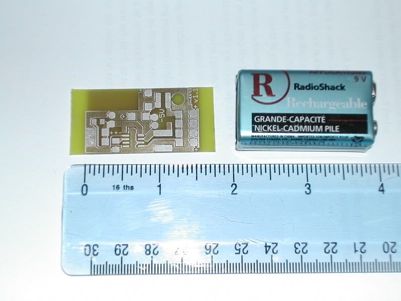
Here's one I did earlier:

http://i100.photobucket.com/albums/m25/kingrs/Inverter_v-11.jpg

I designed this using Eagle, laser printed to techsheet, then UV exposed on a homemade lightbox, its double sided too.
Then removed resist, etched in ferric cloride.
washed, then exposed again to UV using a pad layout.
Then removed resist.
Then tin plated and washed again.
Meggerman
Quote from k c dias on October 25th, 2012, 03:28 PM
Quote from waqas148 on October 25th, 2012, 10:24 AM
I use ferric chloride with 100% success.
Well dog gone!!  Maybe I was using it wrong!  Which end of the bong are you supposed to pour it in to? ;):D:P
Here's one I made earlier:


Sharky

RE: Let's build A "Popper" Noble Gas Engine AKA Ppap Engine.
« Reply #799, on October 26th, 2012, 01:04 AM »
Quote from k c dias on October 23rd, 2012, 12:42 PM
Have a google at this part number: ISL9V3040P3.  These are basically 400V, 21A IGBT's for dummies - 5V logic level gate drive. :)  Send your TTL output through a 1k resistor to the gate input - dat's it, its that easy.  

Below is a photo of the controller.  On the right are the four ISL9V3040P3's for driving the coils (one for each of the three ignition coils, and the forth drives a speaker - a useful tool for detecting misfires).  That right side of the board will likely be cut off of the main board and relocated next to the ignition coils, the 1k resistors will remain on the controller board, and a ribbon cable used for interconnection.  As you can see, that is how I have handled the RF and top cylinder coil switching.
You might consider putting diodes between the resistor and the IGBT's as an extra overpower protection to your driving logic circuit, ... just a thought ;)