VIC testing (Findings and notes)

geenee

RE: VIC testing (Findings and notes)
« Reply #75, on September 20th, 2012, 07:47 PM »Last edited on September 20th, 2012, 07:55 PM by geenee
i watched  many Agha Waqar's's videos.i had problems in English and Pakistan's English accent.i found pdf on wiki(search = Agha Waqar). i need diagram too but he didn't show the circuit, coil, bridge diode, inverter.i saw in his video,has 4 wires connect to wfc, inside the car has big yellow wire, safety bubble water flash back, other videos i saw Agha Waqar's assitant made wfc from old battery.

i thinks he keep this secret.but i think this's all Meyer tech.i will try search that you ask.

http://open-source-energy.org/?tid=661  --> about Agha Waqar 's videos

thanks
geenee

adys15

RE: VIC testing (Findings and notes)
« Reply #76, on September 21st, 2012, 04:28 AM »
Quote from geenee on September 20th, 2012, 07:47 PM
i watched  many Agha Waqar's's videos.i had problems in English and Pakistan's English accent.i found pdf on wiki(search = Agha Waqar). i need diagram too but he didn't show the circuit, coil, bridge diode, inverter.i saw in his video,has 4 wires connect to wfc, inside the car has big yellow wire, safety bubble water flash back, other videos i saw Agha Waqar's assitant made wfc from old battery.

i thinks he keep this secret.but i think this's all Meyer tech.i will try search that you ask.

http://open-source-energy.org/?tid=661  --> about Agha Waqar 's videos

thanks
geenee
Seen the videos!not much of a proof he shows just one jar and one bubbler.To stick a hose in the engine and put people behind the wheel is not a proof,why does not pull the hose out to see the engine stops...One more thing i saw a methane gas tank behind,from what i know the gpl gas sistem conects trough the air inlet of the engine,not trough the fuel inlet.What about the hho management...?what happens with his jar when the car is iddling if the jar  produces lets say 30 lpm how do you control that flow?Stan has 2big boxes full with electronics and this guy shows a little jar and a hose.Even with resonance that he is talking about you need more tubes/cells to prodece enough gas to even idle a car....Untill i don't see some electronics i think is a froud and looking to get his people out of the poverty and to get noticet on media....

geenee

RE: VIC testing (Findings and notes)
« Reply #77, on September 21st, 2012, 05:00 AM »Last edited on September 21st, 2012, 10:21 AM by geenee
Quote from adys15 on September 21st, 2012, 04:28 AM
Quote from geenee on September 20th, 2012, 07:47 PM
i watched  many Agha Waqar's's videos.i had problems in English and Pakistan's English accent.i found pdf on wiki(search = Agha Waqar). i need diagram too but he didn't show the circuit, coil, bridge diode, inverter.i saw in his video,has 4 wires connect to wfc, inside the car has big yellow wire, safety bubble water flash back, other videos i saw Agha Waqar's assitant made wfc from old battery.

i thinks he keep this secret.but i think this's all Meyer tech.i will try search that you ask.

http://open-source-energy.org/?tid=661  --> about Agha Waqar 's videos

thanks
geenee
Seen the videos!not much of a proof he shows just one jar and one bubbler.To stick a hose in the engine and put people behind the wheel is not a proof,why does not pull the hose out to see the engine stops...One more thing i saw a methane gas tank behind,from what i know the gpl gas sistem conects trough the air inlet of the engine,not trough the fuel inlet.What about the hho management...?what happens with his jar when the car is iddling if the jar  produces lets say 30 lpm how do you control that flow?Stan has 2big boxes full with electronics and this guy shows a little jar and a hose.Even with resonance that he is talking about you need more tubes/cells to prodece enough gas to even idle a car....Untill i don't see some electronics i think is a froud and looking to get his people out of the poverty and to get noticet on media....
if you go to president and talk to him "here is success new energy".you must plan carefully??if you lie then you will arrest!!!!

picture i attached,it is inner tube of car tire. wfc--->inner tube-->water flash back arrestor or wfc-->water flash back arrestor--->inner tube

thanks
geenee

adys15

RE: VIC testing (Findings and notes)
« Reply #78, on September 21st, 2012, 05:48 AM »
Quote from geenee on September 21st, 2012, 05:00 AM
Quote from adys15 on September 21st, 2012, 04:28 AM
Quote from geenee on September 20th, 2012, 07:47 PM
i watched  many Agha Waqar's's videos.i had problems in English and Pakistan's English accent.i found pdf on wiki(search = Agha Waqar). i need diagram too but he didn't show the circuit, coil, bridge diode, inverter.i saw in his video,has 4 wires connect to wfc, inside the car has big yellow wire, safety bubble water flash back, other videos i saw Agha Waqar's assitant made wfc from old battery.

i thinks he keep this secret.but i think this's all Meyer tech.i will try search that you ask.

http://open-source-energy.org/?tid=661  --> about Agha Waqar 's videos

thanks
geenee
Seen the videos!not much of a proof he shows just one jar and one bubbler.To stick a hose in the engine and put people behind the wheel is not a proof,why does not pull the hose out to see the engine stops...One more thing i saw a methane gas tank behind,from what i know the gpl gas sistem conects trough the air inlet of the engine,not trough the fuel inlet.What about the hho management...?what happens with his jar when the car is iddling if the jar  produces lets say 30 lpm how do you control that flow?Stan has 2big boxes full with electronics and this guy shows a little jar and a hose.Even with resonance that he is talking about you need more tubes/cells to prodece enough gas to even idle a car....Untill i don't see some electronics i think is a froud and looking to get his people out of the poverty and to get noticet on media....
if you go to president and talk to him "here is success new energy".you must plan carefully??if you lie then you will arrest!!!!

picture i attached,it is inner tube of cat tire. wfc--->inner tube-->water flash back arrestor or wfc-->water flash back arrestor--->inner tube

thanks
geenee
i saw that video too.what is this? a hho filled car  tire tube?for what?storage?

geenee

RE: VIC testing (Findings and notes)
« Reply #79, on September 21st, 2012, 10:45 AM »Last edited on September 21st, 2012, 11:09 AM by geenee
Quote from adys15 on September 21st, 2012, 05:48 AM
Quote from geenee on September 21st, 2012, 05:00 AM
Quote from adys15 on September 21st, 2012, 04:28 AM
Quote from geenee on September 20th, 2012, 07:47 PM
i watched  many Agha Waqar's's videos.i had problems in English and Pakistan's English accent.i found pdf on wiki(search = Agha Waqar). i need diagram too but he didn't show the circuit, coil, bridge diode, inverter.i saw in his video,has 4 wires connect to wfc, inside the car has big yellow wire, safety bubble water flash back, other videos i saw Agha Waqar's assitant made wfc from old battery.

i thinks he keep this secret.but i think this's all Meyer tech.i will try search that you ask.

http://open-source-energy.org/?tid=661  --> about Agha Waqar 's videos

thanks
geenee
Seen the videos!not much of a proof he shows just one jar and one bubbler.To stick a hose in the engine and put people behind the wheel is not a proof,why does not pull the hose out to see the engine stops...One more thing i saw a methane gas tank behind,from what i know the gpl gas sistem conects trough the air inlet of the engine,not trough the fuel inlet.What about the hho management...?what happens with his jar when the car is iddling if the jar  produces lets say 30 lpm how do you control that flow?Stan has 2big boxes full with electronics and this guy shows a little jar and a hose.Even with resonance that he is talking about you need more tubes/cells to prodece enough gas to even idle a car....Untill i don't see some electronics i think is a froud and looking to get his people out of the poverty and to get noticet on media....
if you go to president and talk to him "here is success new energy".you must plan carefully??if you lie then you will arrest!!!!

picture i attached,it is inner tube of car tire. wfc--->inner tube-->water flash back arrestor or wfc-->water flash back arrestor--->inner tube

thanks
geenee
i saw that video too.what is this? a hho filled car  tire tube?for what?storage?
i thinks " low cost storage!!!- -* ".

i already tested VIC's Meyer with 230VAC-rms 50hz of my country(Thailand).my set up is 2 little plates of SS, distill water, 1 diode(1000v50a) 2 choke(from primary of MOT), cfl bulb 13w in series with secondary choke to see amps draw.
result is

1.VIC restrict amps flow 100% because stable dc cannot pass water capacitor.first - cfl light up and second - became dark.mean like charge capacitor when full with stop amps flow.

2.have a bubble in middle plates.this is distill water!!!!!!!i'm very happy this.i never make bubble by distill water.

that proof my opinion.RL low pass filter to make stable DC(straight line DC).stable dc cannot pass distill water.but this test use 50hz frequency of home power.i think resonant will improve gas and more voltage will good.

thanks
geenee

Faisca

RE: VIC testing (Findings and notes)
« Reply #80, on September 21st, 2012, 04:05 PM »Last edited on September 21st, 2012, 04:06 PM by Faisca
Quote from geenee on September 21st, 2012, 10:45 AM
Quote from adys15 on September 21st, 2012, 05:48 AM
Quote from geenee on September 21st, 2012, 05:00 AM
Quote from adys15 on September 21st, 2012, 04:28 AM
Quote from geenee on September 20th, 2012, 07:47 PM
i watched  many Agha Waqar's's videos.i had problems in English and Pakistan's English accent.i found pdf on wiki(search = Agha Waqar). i need diagram too but he didn't show the circuit, coil, bridge diode, inverter.i saw in his video,has 4 wires connect to wfc, inside the car has big yellow wire, safety bubble water flash back, other videos i saw Agha Waqar's assitant made wfc from old battery.

i thinks he keep this secret.but i think this's all Meyer tech.i will try search that you ask.

http://open-source-energy.org/?tid=661  --> about Agha Waqar 's videos

thanks
geenee
Seen the videos!not much of a proof he shows just one jar and one bubbler.To stick a hose in the engine and put people behind the wheel is not a proof,why does not pull the hose out to see the engine stops...One more thing i saw a methane gas tank behind,from what i know the gpl gas sistem conects trough the air inlet of the engine,not trough the fuel inlet.What about the hho management...?what happens with his jar when the car is iddling if the jar  produces lets say 30 lpm how do you control that flow?Stan has 2big boxes full with electronics and this guy shows a little jar and a hose.Even with resonance that he is talking about you need more tubes/cells to prodece enough gas to even idle a car....Untill i don't see some electronics i think is a froud and looking to get his people out of the poverty and to get noticet on media....
if you go to president and talk to him "here is success new energy".you must plan carefully??if you lie then you will arrest!!!!

picture i attached,it is inner tube of car tire. wfc--->inner tube-->water flash back arrestor or wfc-->water flash back arrestor--->inner tube

thanks
geenee
i saw that video too.what is this? a hho filled car  tire tube?for what?storage?
i thinks " low cost storage!!!- -* ".

i already tested VIC's Meyer with 230VAC-rms 50hz of my country(Thailand).my set up is 2 little plates of SS, distill water, 1 diode(1000v50a) 2 choke(from primary of MOT), cfl bulb 13w in series with secondary choke to see amps draw.
result is

1.VIC restrict amps flow 100% because stable dc cannot pass water capacitor.first - cfl light up and second - became dark.mean like charge capacitor when full with stop amps flow.

2.have a bubble in middle plates.this is distill water!!!!!!!i'm very happy this.i never make bubble by distill water.

that proof my opinion.RL low pass filter to make stable DC(straight line DC).stable dc cannot pass distill water.but this test use 50hz frequency of home power.i think resonant will improve gas and more voltage will good.

thanks
geenee
Cool Geenne, but you made ​​no measurements: Volts and current.
I'm not entirely sure, that distilled water begins to ionize and begin to conduct current, especially with high voltage. I did tests with distilled water, because from the beginning I wanted to replicate Meyer, and he used any water.
Now I'm destroying a flyback a monitor (as they have tripler and this hinders), to enjoy the trafo lift.

geenee

RE: VIC testing (Findings and notes)
« Reply #81, on September 21st, 2012, 06:20 PM »Last edited on September 21st, 2012, 08:17 PM by geenee
Quote from Faisca on September 21st, 2012, 04:05 PM
Quote from geenee on September 21st, 2012, 10:45 AM
Quote from adys15 on September 21st, 2012, 05:48 AM
Quote from geenee on September 21st, 2012, 05:00 AM
Quote from adys15 on September 21st, 2012, 04:28 AM
Seen the videos!not much of a proof he shows just one jar and one bubbler.To stick a hose in the engine and put people behind the wheel is not a proof,why does not pull the hose out to see the engine stops...One more thing i saw a methane gas tank behind,from what i know the gpl gas sistem conects trough the air inlet of the engine,not trough the fuel inlet.What about the hho management...?what happens with his jar when the car is iddling if the jar  produces lets say 30 lpm how do you control that flow?Stan has 2big boxes full with electronics and this guy shows a little jar and a hose.Even with resonance that he is talking about you need more tubes/cells to prodece enough gas to even idle a car....Untill i don't see some electronics i think is a froud and looking to get his people out of the poverty and to get noticet on media....
if you go to president and talk to him "here is success new energy".you must plan carefully??if you lie then you will arrest!!!!

picture i attached,it is inner tube of car tire. wfc--->inner tube-->water flash back arrestor or wfc-->water flash back arrestor--->inner tube

thanks
geenee
i saw that video too.what is this? a hho filled car  tire tube?for what?storage?
i thinks " low cost storage!!!- -* ".

i already tested VIC's Meyer with 230VAC-rms 50hz of my country(Thailand).my set up is 2 little plates of SS, distill water, 1 diode(1000v50a) 2 choke(from primary of MOT), cfl bulb 13w in series with secondary choke to see amps draw.
result is

1.VIC restrict amps flow 100% because stable dc cannot pass water capacitor.first - cfl light up and second - became dark.mean like charge capacitor when full with stop amps flow.

2.have a bubble in middle plates.this is distill water!!!!!!!i'm very happy this.i never make bubble by distill water.

that proof my opinion.RL low pass filter to make stable DC(straight line DC).stable dc cannot pass distill water.but this test use 50hz frequency of home power.i think resonant will improve gas and more voltage will good.

thanks
geenee
Cool Geenne, but you made ​​no measurements: Volts and current.
I'm not entirely sure, that distilled water begins to ionize and begin to conduct current, especially with high voltage. I did tests with distilled water, because from the beginning I wanted to replicate Meyer, and he used any water.
Now I'm destroying a flyback a monitor (as they have tripler and this hinders), to enjoy the trafo lift.
i thinks too with you,if make more bubbles between plates, it will conduct current because air's dielectric strength lower than water. from this, Meyer upgrade WFC add duty circle on PLL.to wait water come back again.but in the test didn't have more bubbles and low voltage(230/2 Vrms).if electric pass water but cannot pass air.

1.this is my setup pictures.
2.when turn on power light up.
3.after a little time(0.5s) light drop and gone(see bulb on first pic).
4.1ohm10w resister to measure amps draw.
5.volt=0.05v amps=0.05 amps=50 milliamperes.
6.a little bubble from distilled water(distilled water for battery).if you distill water by yourself, it will be best purest water.

updated
-i tested to measure voltage across cell is 62 VDC. i thinks if voltage of wfc up to 20000v it will be excited.
-reason for use bulb to test be cause i fear short circuit if distilled water conduct electric(but now i known 100% is not conduct stable dc).next step i remove bulb and result is more bubble, amps draw about 80mA.!!!!!! let's test by yourself ,will be excited.!!! choke of Meyer is any choke(Air core,Ferrite core,iron core).all choke act like RL filter like RC low pass filter.to make stable dc low swing range PEAK TO PEAK DC.


thanks
geenee
dennis

RE: VIC testing (Findings and notes)
« Reply #82, on September 21st, 2012, 07:15 PM »
hi all :p I just found this great site yesterday i have a suggestion i dunno if you've thought of this but instead of distilled water or s.s i kinda figured out something that works better get some aluminum plates and anodize them...it makes the outside layer non-conductive connect your wires and silicon around them...i have gotten hydrogen with very little effort...i'm suggesting it might be a better idea too test your vic circuits on this cuz it has zero leakage...or maybe you have good cells :P

geenee

RE: VIC testing (Findings and notes)
« Reply #83, on September 21st, 2012, 08:26 PM »Last edited on September 21st, 2012, 09:03 PM by geenee
Quote from dennis on September 21st, 2012, 07:15 PM
hi all :p I just found this great site yesterday i have a suggestion i dunno if you've thought of this but instead of distilled water or s.s i kinda figured out something that works better get some aluminum plates and anodize them...it makes the outside layer non-conductive connect your wires and silicon around them...i have gotten hydrogen with very little effort...i'm suggesting it might be a better idea too test your vic circuits on this cuz it has zero leakage...or maybe you have good cells :P
that's great.that's my old thought(http://open-source-energy.org/?tid=563) but it's work,like you suggested.

updated
-when i remove cfl bulb then i measure voltage across WFC.voltage is 95VDC.amps draw 70-80mA.more bubbles than first test.let's test this all.

thanks
geenee

Faisca

RE: VIC testing (Findings and notes)
« Reply #84, on September 22nd, 2012, 10:04 AM »Last edited on September 22nd, 2012, 10:05 AM by Faisca
Quote from geenee on September 21st, 2012, 08:26 PM
Quote from dennis on September 21st, 2012, 07:15 PM
hi all :p I just found this great site yesterday i have a suggestion i dunno if you've thought of this but instead of distilled water or s.s i kinda figured out something that works better get some aluminum plates and anodize them...it makes the outside layer non-conductive connect your wires and silicon around them...i have gotten hydrogen with very little effort...i'm suggesting it might be a better idea too test your vic circuits on this cuz it has zero leakage...or maybe you have good cells :P
that's great.that's my old thought(http://open-source-energy.org/?tid=563) but it's work,like you suggested.

updated
-when i remove cfl bulb then i measure voltage across WFC.voltage is 95VDC.amps draw 70-80mA.more bubbles than first test.let's test this all.

thanks
geenee
Then Geenee, this is a lot of current (even in distilled water). I calculated, and in both cases the resistance of the cell was = 1240 ohms. Even if you remain linear with increasing voltage (I doubt, the tendency is to fall), when you apply, more than 1200 V, the current will be = 1 A. (or more) power than 1Kwatt.
So we're back to square one. Maybe with bidistilled water, can decrease the current in mA. even in kVolts. But this water will be as precious as gasoline and do not want that.
I still can not make stuff for my experiment, in which I know I can by KVolts with almost zero current (> 2kV /< 5mA.). Just do not know if gas does. Just experimenting.
Good luck

geenee

RE: VIC testing (Findings and notes)
« Reply #85, on September 22nd, 2012, 10:52 AM »Last edited on September 22nd, 2012, 10:56 AM by geenee
my water is not pure(distilled water for battery).it's leak current.then amps will increase linear like you said.in stable DC cannot pass normal capacitor and water too. that's important.

next step i have problems about DCHV.i need 140000v for 2 mm gap(dielectric strength 70000v/1mm),breakdown point.how to do that??i have a 10KV(AC) circuit but it's not enough.if water capacitor has 10nF and charge to 140000V that a huge of energy!!!!98 Joule.charge Q=0.0014 Coulombs.need a huge of Amps from primary side.maybe need a over unity unit to charge water capacitor from primary side to that breakdown point!!!!!!

Faisca,i like your all videos.great experiment about high voltages.let's test that.need help!!!

thanks
geenee  


dennis

RE: VIC testing (Findings and notes)
« Reply #86, on September 22nd, 2012, 11:48 AM »
Quote from geenee on September 21st, 2012, 08:26 PM
Quote from dennis on September 21st, 2012, 07:15 PM
hi all :p I just found this great site yesterday i have a suggestion i dunno if you've thought of this but instead of distilled water or s.s i kinda figured out something that works better get some aluminum plates and anodize them...it makes the outside layer non-conductive connect your wires and silicon around them...i have gotten hydrogen with very little effort...i'm suggesting it might be a better idea too test your vic circuits on this cuz it has zero leakage...or maybe you have good cells :P
that's great.that's my old thought(http://open-source-energy.org/?tid=563) but it's work,like you suggested.

updated
-when i remove cfl bulb then i measure voltage across WFC.voltage is 95VDC.amps draw 70-80mA.more bubbles than first test.let's test this all.

thanks
geenee
i guess this is probably not the right thread to discuss this but:)... from what i've read and understand the conditioning process is basically slowly pulling the chromium in the s.s too the surface thus actually insulating the outside layer...if this is indeed whats happening then you can very easily bypass all the work of conditioning by using alum and having someone anodize it for you or look it up and do it yourself its basically a acid bath with electrolysis or something. I don't see the cell working if the conditioning layer isn't there unless ur using distilled water(which isn't very realistic) also i was wondering, when i started out i was basically following the pjkbook.pdf eBook floating around ....now it all seems out too lunch now...but i was following the concept of cutting notches into the pipes to make the pitches match, if its a capacitor then why is that relevant, is this indeed part of stans design. maybe the 3 inch cell design i saw in the rebuild guides is notched to match the both pipes frequency's also, has this been considered?  could this have an effect on the vic coils output signal.


Amsy

RE: VIC testing (Findings and notes)
« Reply #87, on September 22nd, 2012, 12:29 PM »
hy folks,

I saw the threads about your actual tests. Also at this time I make tests with MOTs and a little WFC. The WFC is a spark plug with very little electrode surface.

The MOT is my "VIC" and I can reach at ~300Watts ionisation of the hydrogen gas which is built on the - electrode. The evidence of the ionisation of the hydrogen is because there are sparks around the - electrode which are dark violett and ultraviolett.

During ionisation there happens a stealing of electrones out of the hydrogen. That reduces the current which has to be feed in. An importnant point is the floating ground of the secondary, then the stealed electrons can not reach the input of the houseelectric. But I will build in also a filter http://en.wikipedia.org/wiki/Line_filter

https://www.google.at/search?q=line+filter&hl=de&prmd=imvns&source=lnms&tbm=isch&sa=X&ei=khBeUNLYMsWL4gS2iIGICA&ved=0CAcQ_AUoAQ&biw=1280&bih=671

So the discharges in the water and the stealed electrones (HF interference) cannot leave the circuit.

Ciao

geenee

RE: VIC testing (Findings and notes)
« Reply #88, on September 22nd, 2012, 04:55 PM »Last edited on September 22nd, 2012, 04:55 PM by geenee
Dennis, i don't know about relation between notches sound vibration resonant inside cell, hard to understand that.lets's see in wave guide thread.maybe helped.

Amsy,please explain your work.like picture, diagrams.how to steal electron from water?i will try too!!!

thanks
geenee

Webmug

RE: VIC testing (Findings and notes)
« Reply #89, on December 4th, 2012, 04:56 AM »Last edited on December 4th, 2012, 05:48 AM by Webmug
Quote from Webmug on August 30th, 2012, 09:46 AM
Quote from Sharky on August 20th, 2012, 05:32 AM
Quote from Webmug on August 15th, 2012, 07:25 AM
Hi,

I'm posting this message here to lead you to ionizationx.com because I don't want to post a copy of a thread twice.

This could be the working principle of the Resonance VIC transformer and also the Injector VIC unit since it is a follow up improved version.
Quote from http://www.ionizationx.com/index.php/topic,2488.msg23224.html#msg23224
The VIC is a system for restricting the flow of amperes while allowing voltage electrical stress to be propagated. It uses a principle called the electron bounce phenomenon, that is simply the separation of charges in conductor materials under time varying magnetic fields. For this a pulse is applied and is compressed during the collapse the field in its coils.
Let me know what you think!

It involves the EbP Electron Bounce Phenomenon and Electron Clustering.

If there are few members who can not access the ionizationx site I would post the thread here if required.

Cheers!!!

Br,
Webmug
Hi Webmug,
Your results are very interesting indeed, the scope shots where you do not have the wfc connected seem almost perfect step charging images. You state that when you connect the wfc that the signal is not at all there anymore but could you post it anyways?

Allthough i have quite some electrical engineering knowlegde some things are difficult for me to grasp (guess happens to all of us sometimes :cool: ). Could you try to enlighten me a bit on what exactly triggers the electron bounce phenomena? I do understand why it could trigger amp restriction but i do not understand what makes the copper ions and electrons cluster on opposite sides of the coil? As far as my knowlegde reaches the only resistance to amp flow was the actual copper wire resistance itself. Do you know of any, non-meyer, information source about the ebp in inductive coils?

Thank you,
Sharky
Sharky,

Here are my scope shots!

First the open circuit measured;


positive choke B+ connected to WFC plate, B- open;


negative choke B- connected to WFC plate, B+ open;


chokes connected to both B+ and B- connected to WFC;


PULSE on the same frequency and GATE duty cycle and period are fixed except when the WFC is connected frequency is lower.

Regards
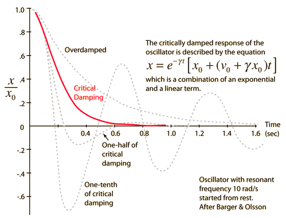
Above is a "Damped Oscillator".

http://www.ionizationx.com/index.php/topic,2488.msg23226.html#msg23226

Index
http://farside.ph.utexas.edu/teaching/315/Waves/node8.html
Transient Oscillator Response
http://farside.ph.utexas.edu/teaching/315/Waves/node14.html


Question:
What will happen when we force a "Critically Damped Oscillator" near resonance?


Is this the PFN part?


Regards,
Webmug

Amsy

RE: VIC testing (Findings and notes)
« Reply #90, on December 4th, 2012, 05:55 AM »
Quote from geenee on September 22nd, 2012, 04:55 PM
Dennis, i don't know about relation between notches sound vibration resonant inside cell, hard to understand that.lets's see in wave guide thread.maybe helped.

Amsy,please explain your work.like picture, diagrams.how to steal electron from water?i will try too!!!

thanks
geenee
Hi geenee,

basically for testing of the ionization and collecting experience it is possible to do this with a Spark plug. My test setup worked with a spark plug with 5kOhm Resistor inside.
So you put the spark plug on the secondary side of a MOT with a diode like the VIC is.
Then you should take a variac for the primary side to controll the voltage, that you can try different voltages. Be carefull, the secondary of the MOT can kill you.

The spark plug can be immersed in destilled water. It also work other water. You should keep the current down on the secondary side smaler than 0.5A.

Make brakes during testing, the spark plug is getting warm and also the MOT.
The 0.5A is a little current, but can bring electrolyses in the first step. This builds H2 on the cathode (-) and that will be ionized because of the voltage.
You can see sparks and it makes deep noises during ionization.

Keep in mind: be carfull! Always plug of the MOT and Variac when making changes to the system.


Rider

RE: VIC testing (Findings and notes)
« Reply #91, on December 4th, 2012, 07:34 AM »
Dear Webmug and Sharky,

Short question on these interesting scope views.
Is the choke in the circuit made of copper or SS wire?

Cheers,  Rider


Rider

RE: VIC testing (Findings and notes)
« Reply #93, on December 4th, 2012, 07:40 AM »
Quote from Webmug on December 4th, 2012, 07:35 AM
Quote from Rider on December 4th, 2012, 07:34 AM
Dear Webmug and Sharky,

Short question on these interesting scope views.
Is the choke in the circuit made of copper or SS wire?

Cheers,  Rider
Rider,
Choke is made of Copper wire.

Br,
Webmug
Hi Webmug,  According to Stan (video in new zealand) amp restriction is done by high restrictive wire choke.  Therefore has to be SS-wire.  Do you or sharky have access to this wire?

Rider

Webmug

RE: VIC testing (Findings and notes)
« Reply #94, on December 4th, 2012, 07:43 AM »
Quote from Rider on December 4th, 2012, 07:40 AM
Quote from Webmug on December 4th, 2012, 07:35 AM
Quote from Rider on December 4th, 2012, 07:34 AM
Dear Webmug and Sharky,

Short question on these interesting scope views.
Is the choke in the circuit made of copper or SS wire?

Cheers,  Rider
Rider,
Choke is made of Copper wire.

Br,
Webmug
Hi Webmug,  According to Stan (video in new zealand) amp restriction is done by high restrictive wire choke.  Therefore has to be SS-wire.  Do you or sharky have access to this wire?

Rider
Yes, there are two versions of a VIC. The one I'm referring (scope shots) to has copper wire. The Injector VIC has SS wire.

Br,
Webmug

Rider

RE: VIC testing (Findings and notes)
« Reply #95, on December 4th, 2012, 07:50 AM »
Quote from Webmug on December 4th, 2012, 07:43 AM
Quote from Rider on December 4th, 2012, 07:40 AM
Quote from Webmug on December 4th, 2012, 07:35 AM
Quote from Rider on December 4th, 2012, 07:34 AM
Dear Webmug and Sharky,

Short question on these interesting scope views.
Is the choke in the circuit made of copper or SS wire?

Cheers,  Rider
Rider,
Choke is made of Copper wire.

Br,
Webmug
Hi Webmug,  According to Stan (video in new zealand) amp restriction is done by high restrictive wire choke.  Therefore has to be SS-wire.  Do you or sharky have access to this wire?

Rider
Yes, there are two versions of a VIC. The one I'm referring (scope shots) to has copper wire. The Injector VIC has SS wire.

Br,
Webmug
Hmm, these same scopeshots with the Injector VIC connected might be very interesting then since it looks everything else is working.
(I assume you mean the delrin VIC bobbin with the EI laminated core according to Dynodon with the 2 spools that fit together.)

Rider

Webmug

RE: VIC testing (Findings and notes)
« Reply #96, on December 4th, 2012, 07:54 AM »
Quote from Rider on December 4th, 2012, 07:50 AM
Quote from Webmug on December 4th, 2012, 07:43 AM
Quote from Rider on December 4th, 2012, 07:40 AM
Quote from Webmug on December 4th, 2012, 07:35 AM
Quote from Rider on December 4th, 2012, 07:34 AM
Dear Webmug and Sharky,

Short question on these interesting scope views.
Is the choke in the circuit made of copper or SS wire?

Cheers,  Rider
Rider,
Choke is made of Copper wire.

Br,
Webmug
Hi Webmug,  According to Stan (video in new zealand) amp restriction is done by high restrictive wire choke.  Therefore has to be SS-wire.  Do you or sharky have access to this wire?

Rider
Yes, there are two versions of a VIC. The one I'm referring (scope shots) to has copper wire. The Injector VIC has SS wire.

Br,
Webmug
Hmm, these same scopeshots with the Injector VIC connected might be very interesting then since it looks everything else is working.
(I assume you mean the delrin VIC bobbin with the EI laminated core according to Dynodon with the 2 spools that fit together.)

Rider
http://open-source-energy.org/forum/attachment.php?aid=2128

Br,
Webmug

Rider

RE: VIC testing (Findings and notes)
« Reply #97, on December 4th, 2012, 08:02 AM »
Quote from Webmug on December 4th, 2012, 07:54 AM
Quote from Rider on December 4th, 2012, 07:50 AM
Quote from Webmug on December 4th, 2012, 07:43 AM
Quote from Rider on December 4th, 2012, 07:40 AM
Quote from Webmug on December 4th, 2012, 07:35 AM
Rider,
Choke is made of Copper wire.

Br,
Webmug
Hi Webmug,  According to Stan (video in new zealand) amp restriction is done by high restrictive wire choke.  Therefore has to be SS-wire.  Do you or sharky have access to this wire?

Rider
Yes, there are two versions of a VIC. The one I'm referring (scope shots) to has copper wire. The Injector VIC has SS wire.

Br,
Webmug
Hmm, these same scopeshots with the Injector VIC connected might be very interesting then since it looks everything else is working.
(I assume you mean the delrin VIC bobbin with the EI laminated core according to Dynodon with the 2 spools that fit together.)

Rider
http://open-source-energy.org/forum/attachment.php?aid=2128

Br,
Webmug
This picture is from the copper chokes.  So, I mean the other one.

IED

RE: VIC testing (Findings and notes)
« Reply #98, on December 4th, 2012, 10:28 AM »
Quote from Webmug on December 4th, 2012, 04:56 AM
Quote from Webmug on August 30th, 2012, 09:46 AM
Quote from Sharky on August 20th, 2012, 05:32 AM
Quote from Webmug on August 15th, 2012, 07:25 AM
Hi,

I'm posting this message here to lead you to ionizationx.com because I don't want to post a copy of a thread twice.

This could be the working principle of the Resonance VIC transformer and also the Injector VIC unit since it is a follow up improved version.
Quote from http://www.ionizationx.com/index.php/topic,2488.msg23224.html#msg23224
The VIC is a system for restricting the flow of amperes while allowing voltage electrical stress to be propagated. It uses a principle called the electron bounce phenomenon, that is simply the separation of charges in conductor materials under time varying magnetic fields. For this a pulse is applied and is compressed during the collapse the field in its coils.
Let me know what you think!

It involves the EbP Electron Bounce Phenomenon and Electron Clustering.

If there are few members who can not access the ionizationx site I would post the thread here if required.

Cheers!!!

Br,
Webmug
Hi Webmug,
Your results are very interesting indeed, the scope shots where you do not have the wfc connected seem almost perfect step charging images. You state that when you connect the wfc that the signal is not at all there anymore but could you post it anyways?

Allthough i have quite some electrical engineering knowlegde some things are difficult for me to grasp (guess happens to all of us sometimes :cool: ). Could you try to enlighten me a bit on what exactly triggers the electron bounce phenomena? I do understand why it could trigger amp restriction but i do not understand what makes the copper ions and electrons cluster on opposite sides of the coil? As far as my knowlegde reaches the only resistance to amp flow was the actual copper wire resistance itself. Do you know of any, non-meyer, information source about the ebp in inductive coils?

Thank you,
Sharky
Sharky,

Here are my scope shots!

First the open circuit measured;


positive choke B+ connected to WFC plate, B- open;


negative choke B- connected to WFC plate, B+ open;


chokes connected to both B+ and B- connected to WFC;


PULSE on the same frequency and GATE duty cycle and period are fixed except when the WFC is connected frequency is lower.

Regards
Above is a "Damped Oscillator".

http://www.ionizationx.com/index.php/topic,2488.msg23226.html#msg23226

Index
http://farside.ph.utexas.edu/teaching/315/Waves/node8.html
Transient Oscillator Response
http://farside.ph.utexas.edu/teaching/315/Waves/node14.html


Question:
What will happen when we force a "Critically Damped Oscillator" near resonance?


Is this the PFN part?


Regards,
Webmug
Interesting scope shots as the only ones I have ever seen like this where from here: http://youtu.be/GnpPhfVBsXM.
Question, was the VIC transformer hooked up to a WFC during the test? I went ahead and gave that guy my support as the WFC he has looks like he has done his homework big time and I need something like that for my testing of this technology. I just hope he gets more sold as he told me that he might have to issue me a refund if he can't get 10 sold from here: http://www.truegreensolutions.net/index.php?p=1_32_Exciter-Array

Seems like real progress is finally being made on this technology :)

Regards,
IED