I have seen him logged on a few days ago.
VIC v5 driver board order list
Why Ronnie dont help us?
Matt
Why in the last part of your video when you connected pick-up coil , the frequency is not stable but little change up and down?
Thank Matt
Why in the last part of your video when you connected pick-up coil , the frequency is not stable but little change up and down?
Thank Matt
It's hunting andy, since I'm not exactly centered on it.
Matt
Can you explain it more , please?
Is the resonant frequency of pick-up coil constantly changing?
Can you explain it more , please?
Is the resonant frequency of pick-up coil constantly changing?
Possibly, though I think what you are seeing is an overshoot of the PLL. What happens is the VCO adjusts a little too high, then overcompensates by adjusting a little too low. This goes back-n-forth forever. This overshoot can be minimized if your center frequency exactly matches the frequency the PLL is tracking, it can never be eliminated though, since that's the whole purpose of a PLL to hunt and track the frequency of the feedback. With a change in component values, you can slow down how rapidly the PLL adjusts. When you do that though, it becomes impossible for the PLL to adjust quickly. Comes down to a basic engineering trade-off.
What you don't want to happen is have your VIC running at full power and have something change and the PLL not respond quickly enough. The end result would be burned up wires inside the VIC. The values Stan chose are likely that way for a reason.
What you don't want to happen is have your VIC running at full power and have something change and the PLL not respond quickly enough. The end result would be burned up wires inside the VIC. The values Stan chose are likely that way for a reason.
Thank Matt for explanation. Do you have tested your driver board with coils from Russ?
I have not yet. Still researching a suitable test cell to connect up to the VIC.
Matt
If you connect the board to complete VIC and WFC what the PLL will be hunting?
Self resonant frequency of the L1?
If you connect the board to complete VIC and WFC what the PLL will be hunting?
Self resonant frequency of the L1?
The PLL will be trying to track the frequency it sees from the feedback coil. What exactly that frequency is, I'm not sure. The VIC is a dynamic component.
When I was putting the design for this driver together, it occurred to me we can have frequency doubling. If the feedback actually sees this frequency doubling, we may have a problem. To resolve this I considered adding a divider (divide by two), but didn't carry through with this thought, since I'm still uncertain. What a /2 would actually do is make the VCO run at half the frequency of the feedback signal. This may still end up being something that is needed, just don't know yet.
When I was putting the design for this driver together, it occurred to me we can have frequency doubling. If the feedback actually sees this frequency doubling, we may have a problem. To resolve this I considered adding a divider (divide by two), but didn't carry through with this thought, since I'm still uncertain. What a /2 would actually do is make the VCO run at half the frequency of the feedback signal. This may still end up being something that is needed, just don't know yet.
But Stan dont use a divider (divide by two).
When I was putting the design for this driver together, it occurred to me we can have frequency doubling. If the feedback actually sees this frequency doubling, we may have a problem.
"Frequency doubling" is a phenomenon Stan used to describe an effect from the VIC transformer. Would be best to translate that into an established electrical engineering term once the phenomenon is known.
andy
Re: VIC v5 driver board order list
« Reply #87, on September 24th, 2017, 06:05 PM »Last edited on September 25th, 2017, 08:11 AM
The Frequency doubling occured in Henne testing and we see it in the scope shots he posted.
Driver board dont have problem with it.
Driver board dont have problem with it.
HMS-776
Re: VIC v5 driver board order list
« Reply #88, on September 25th, 2017, 07:09 PM »Last edited on September 25th, 2017, 09:57 PM
Matt, I have a question regarding the circuit.
What is the minimum &maximum current that the current sense transformer can sense and use to effectively achieve a phase lock?
UPDATE: Did some testing tonight, VIC is working as it should and coils are now oriented correctly. With the sec coil open I'm seeing ringing at 17.24kHz and at voltages which match my turns ratio calculations.
What's interesting is when I connect the chokes and measure across them....When the primary coil goes high I see ringing at one frequency and when the primary coil goes low I see ringing at a higher frequency. The ratio of the ringing frequencies matches the ratio difference of my chokes. Got me really excited as it verified some of my thinking from last year
HMS
What you mean by : " the primary coil goes high" and by : "the primary coil goes low"
Goes high in voltage or in frequency?
Thank
What you mean by : " the primary coil goes high" and by : "the primary coil goes low"
Goes high in voltage or in frequency?
Thank
HMS-776
Re: VIC v5 driver board order list
« Reply #90, on September 26th, 2017, 04:02 AM »Last edited on September 26th, 2017, 05:27 AM
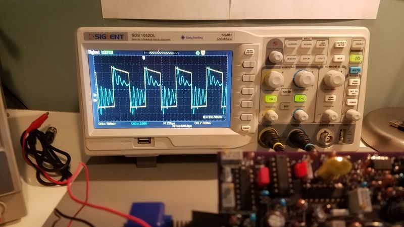 Voltage, when the square wave is high.
 Yellow trace is primary coil, blue is chokes ringing with no cell connected.
The yellow trace didn't have a flat top as I needed to change the voltage, I just took the screenshot before I adjusted it.
Matt Watts
Re: VIC v5 driver board order list
« Reply #91, on September 26th, 2017, 07:10 AM »Last edited on September 26th, 2017, 07:38 AM
Matt, I have a question regarding the circuit.
What is the minimum &maximum current that the current sense transformer can sense and use to effectively achieve a phase lock?
The comparator senses the zero cross point. So by trial-n-error you will want to use the very minimal current possible. I have no real idea what the maximum is, but I'm certain at some point things will self destruct. The whole point of using a current sense transformer for the feedback is to ensure there is clean signal, which is normally pretty difficult to do when you're tied into a high voltage source. I've used this same mechanism for driving Tesla coils and it works really slick.
My rule of thumb is to start with a resistor inline, say 10k ohms and work down until the lock is solid. If you're careful, you can put a probe on the feedback pin and watch for a nice clean square wave. Having this, the PLL will have a good clean signal to lock onto. What I mean by "inline" is you form a loop. You have the pickup coil winding on your VIC. Take one end of this through the current sense transformer, then connect it to a resistor and finally back to the other end of your pickup transformer. The less current in this loop, the less your pickup coil interferes with the normal operation of your VIC.
HMS-776
Re: VIC v5 driver board order list
« Reply #92, on September 26th, 2017, 08:39 PM »Last edited on September 27th, 2017, 07:04 PM
Ok, makes sense.....
I wound a pickup coil today. Unfortunately the UY1568 cores have a small area...I ended up winding 60 turns directly on top of the primary coil.
Not sure if it will work but its a start. I worry about the effect the coupling might have on the rest of the circuit.
Tomorrow I'll do some testing with the feedback coil to see if it works.
HMS-776
Re: VIC v5 driver board order list
« Reply #93, on September 27th, 2017, 07:05 PM »Last edited on September 27th, 2017, 08:20 PM
UPDATE: I tried using the VIC 5.0 circuit to find and lock to the VIC resonance with the cell connected.
I measured my 60 turn feedback coil wound directly on top of the primary coil...Result is 400uH and .335 ohms.
I added a 47 ohm resistor as well as a 2k pot to see what would give me the best feedback signal....While adjusting the 2k pot the frequencies changed from scanning to a 1kHz freq, this happened when total R was around 250 ohms, once I got above 250 ohms the feedback circuit basically stops working. I found the 47 ohm R allows for a good feedback signal at the voltages I'm driving my coil at.
There is much more to consider here such as my primary feedback turns ratio etc...But so far this is what I'm seeing.
I can get about 55V's across the cells at this point but no resonance....I believe my inability to hit resonance is due to my coils not being properly balanced. The work continues.
Matt, question for you, how did you implement the adjustment for the TIP120 duty cycle rollof?
HMS
Do you tried introducing the air gap in the core?
Do you tried introducing the air gap in the core?
Yes, my core is gapped. I rechecked my coils and they match up to my math. Not exactly the same as Stan's but close.
More testing to come.
More testing to come.
Matt, question for you, how did you implement the adjustment for the TIP120 duty cycle rollof?
Thanks Matt,
So I did more testing tonight. I determined that I need to change my feedback coil specs or location on the VIC.
The circuit locks when using a signal from my freq gen but as soon as I connect it to my feedback coil it goes to the baseline freq of 1kHz and stays there.
I noticed that if I turn the amplitude or duty cycle down too low on my freq gen the circuit will also go back to the 1kHz baseline. Using a 47 ohm resistor I can't go below 7V peak or less than 60% duty cycle without the circuit going to the 1kHz and staying there.
More work ahead....Also Matt, if you order more boards let me know. I want to make one using bigger pots and BNC connectors, thanks.
haxar
Re: VIC v5 driver board order list
« Reply #98, on October 17th, 2017, 04:43 AM »Last edited on October 17th, 2017, 05:06 AM
Looks like Mouser may have messed up my backorder.
http://www.mouser.com/ProductDetail/KEMET/MMK5104K50J01L4BULK/
This part was in stock during the term of my backorder. I got a status update on the order telling me I would have to wait until December 4th for this one, while waiting on the Nichicon 0.33uF film cap.
Order email:Quote I'll place an order with another supplier if this is true.
http://www.mouser.com/ProductDetail/KEMET/MMK5104K50J01L4BULK/
This part was in stock during the term of my backorder. I got a status update on the order telling me I would have to wait until December 4th for this one, while waiting on the Nichicon 0.33uF film cap.
Order email:
Hi,
The 80-MMK5104K50J01L4 was in stock during the term of this backorder. Was the quantity of 10 included in this order _before_ they went out of stock again? Or would I have to wait until December 4?
These components are taking a long time to manufacture.
Yep, they didn't pull the part while it was in stock.