VIC v5 driver board order list

HMS-776

Re: VIC v5 driver board order list
« Reply #100, on October 17th, 2017, 07:06 PM »
That sucks dude,

I waited a few months to get all my stuff as well. Might want to change or delete the order then reorder it without that cap.


I'm hoping to see the observations of others testing this circuit. I am not sure what to do about the voltage/current issue I'm seeing on the pickup/ feedback circuit. I'm using the U1658 cores and there's only room for two coils on them...


Matt Watts

Re: VIC v5 driver board order list
« Reply #102, on November 14th, 2017, 01:31 PM »
Good deal Hax.  Check everything a couple of times more, then connect it to a current limited power source and crank-r up.

Henne

Re: VIC v5 driver board order list
« Reply #103, on November 15th, 2017, 05:45 AM »
Curious as to see what results other people will get with this new VIC driver setup.

Just to provide some context as to why I've been quiet for a while. I bumped into limitations with my lab setup. The conclusion was that I need a better oscilloscope, meters, better testing equipment overal, etc... But my budget ran out and, as you know, these things don't come cheap. Right now my goal is to get more money together to dedicate to this project. I took on another assignment to achieve that goal that currently requires my full attention. I will surely come back to this project in due time.

In the meantime I will keep checking the forum to check the results of other people working with this board. ;) Looking forward to reading/hearing about it! Sharing is caring! ;)

Henne

Re: VIC v5 driver board order list
« Reply #104, on November 15th, 2017, 05:52 AM »
Just for reference, I drove the board pretty hard, but I was unable to produce any gas. One of the things I would try next, is to use (double) distilled water in the WFC. It's just one of the many parameters of the WFC and VIC setup. Everything needs to be spot on, but not everything is easily 'tunable'. I hope testing with different water conductivities might yield different results.

My 2 cents.

HMS-776

Re: VIC v5 driver board order list
« Reply #105, on November 15th, 2017, 09:29 PM »
Glad that there are still a few of us working on this.

I've all but given up, not even sure what step to take next. I just put all my lab stuff away the other day as we had a guest staying in that room. I'm not sure if I even want to take it back out: (

I feel I have tried everything and have yet to see any results. Its been over 10 years now,  I just wish I knew where my mistake was...

Perhaps its time to share more info and brainstorm as a team again?

~Russ

Re: VIC v5 driver board order list
« Reply #106, on November 16th, 2017, 12:52 PM »
To both of you.

Thank you. For I also have detacated so much time resorces and efforts. 

In the end a lack of knolage is there.

Brain storming as a team is allways helpfull.

Its the main reasion why this forums. Is here. None of us can do it alone. Not even Stan!!!

Its OUR forum. 

For me some Times a breake is needed.  To let it set for a while is verry helpfull for me.

I have even not given up. But rather.  Taking time to think. New incites will come. Better understandings to come.  In due time.

We will get it.

~Russ

Hardkrome

Re: VIC v5 driver board order list
« Reply #107, on November 16th, 2017, 04:42 PM »
Quote from HMS-776 on November 15th, 2017, 09:29 PM
Glad that there are still a few of us working on this.

I've all but given up, not even sure what step to take next. I just put all my lab stuff away the other day as we had a guest staying in that room. I'm not sure if I even want to take it back out: (

I feel I have tried everything and have yet to see any results. Its been over 10 years now,  I just wish I knew where my mistake was...

Perhaps its time to share more info and brainstorm as a team again?
The best way, is to ignore these people and build it the way Stan says it works. Change the way you think. IT is a very exciting technology, but not for public consumption. Whenever I took anything any of them have said with value. That info set me back another year. ALL of them are blowing smoke. Believe me on that.

p.s. Throw that vic circuit and transformer in a box because its the last thing you will need.


securesupplies

Re: VIC v5 driver board order list
« Reply #108, on January 7th, 2018, 01:12 AM »Last edited on January 7th, 2018, 01:15 AM
Quote from HMS-776 on November 15th, 2017, 09:29 PM
Glad that there are still a few of us working on this.

I've all but given up, not even sure what step to take next. I just put all my lab stuff away the other day as we had a guest staying in that room. I'm not sure if I even want to take it back out: (

I feel I have tried everything and have yet to see any results. Its been over 10 years now,  I just wish I knew where my mistake was...

Perhaps its time to share more info and brainstorm as a team again?
========================================
========================================
 :) :) :) :) :) :) :) :) :) :) :) :) :) :) :) :) :) :) :) :) :) :) :) :) :) :) :

HAPPY NEW YEAR 2018    -
NEW RESOLUTION HAVE THIS FULL COMPLETE AND RE DOCUMENTED PROMOTED AND VIDEOS BEFORE 2020

We are Working   we can lower the  thresh hold and raise tun ability stability this way

Have a Great Year and Do Great Things

Add the  Dielectric barrier to it now

https://youtu.be/IDth0hPv-1g

o Focusing we must publish which has be dielectric, properties and will now dissolve and enter water from h2 exposure etc or degrade, and which is malleable for the different cell types tube cell wet , tube cell dry, wet cell plate,(browns) (meyers) and plate dry we can compare and fine tune the data here and post,

 so far we have
 mica paper/ plates or mica dielectric ? k volts per mm

Glass tube or plate ? mm ( from ozone machine type manufacture) , dielectric ? k volts per mm

The Ozone Glass Factory states ( Electric insulation: 10000 times of usual glass) But does not state k per mm

=======================
 Let study look at dielectric k volts per mm and stability if in water or h2 please pose what you find on each above reply we can work out bet thinnest result
  Stan Meyer Tall Wet Cell Tubes ( longer the tubes more gas yields) 9 Cell

The Critical InFo you Want

Outer tubes 1 inch diameter,
inner tubes 3/4 inch diameter
Thickness 1/16 inch
316 L Stainless Steel. or higher.
16 to 18 inches long 418 mm to 458 mm
Gap 1mm to 2mm
9 Tube sets ( 18 Tubes inner and outer)
 
 Sta Meyer 11 Cell Wet Cell Tubes the anode and cathode SS tube and rod. I will begin there. 1/2" rod and 3/4" tubing. The rod will be cut down to 4" in length with the slots milled and drilled on the ends. The tube is .035" wall which will be machined down to .030" wall and 2.75" in length.

  Plates wet cell are 12.5 cm diameter as a start size
  so the glass tubes or plates of mica etc starting point Tubes 20 mm diameter inner 9 Tube Wet Cell Meyers) & 13 mm diameter inner ( 11 Cell design wet cell meyers)

2 Disc or square 12.5 cm and 8 cm diameter ( plate wet cell Brownes and or meyers

Please not these sizes are guesstimates we want the glass or coating to be on touching sealed to cathode if that is center tube rod so fitment is tighter the better  , so some advise eon precise sizes need fine tuning here and positing

Coffee Time
 O:-)

Ref video
Tony Quinn  and Valentin Petkov /valyonpz/
Dan Secure Supplies


chris skuld

Re: VIC v5 driver board order list
« Reply #109, on March 1st, 2018, 11:55 PM »
hi all

how to tune this board?  I saw Matt's video but my english listening is suck :(

by the way, does anyone generate gas successfully from this board? :)

Matt Watts

Re: VIC v5 driver board order list
« Reply #110, on March 3rd, 2018, 12:01 AM »
I'm not certain I can add a subtitle overlay to my video, but maybe I can scratch something out that will help.

chris skuld

Re: VIC v5 driver board order list
« Reply #111, on March 3rd, 2018, 12:33 AM »
hi Matt, maybe I should do more research and ask,  sorry for saying that like a begger.

but i don't know how to delete the post :-/

Matt Watts

Re: VIC v5 driver board order list
« Reply #112, on March 3rd, 2018, 12:49 AM »
No worries Chris.  I remember the struggle I went through trying to decipher Russian when I was working on the Ruslan device.  I think I remember one word:  Zimmer means ground.


securesupplies

Re: VIC v5 driver board order list
« Reply #114, on March 8th, 2018, 09:42 PM »

Board Assembled in Australia
Small team learning about the Vic now

Others joining in about 15 people spread out there

Dan

OLHU

Re: VIC v5 driver board order list
« Reply #115, on May 19th, 2018, 11:28 PM »
  Hi Matt and all
I put my board together over the Christmas  break and back on it again. As Ronnie would say "Just a little bit more time".
I have been playing around with it to get to a 50% duty cycle and found R6.3 resister would need about 470K. The LED flashes rather than locked on, I guess the 50% D/Cycle is causing it. Also, found the Delay adjustment interacts with the duty cycle. I am looking at having a delay range of 20 - 25 cycle/sec. and 50% duty Cycle.


OLHU

Re: VIC v5 driver board order list
« Reply #116, on May 19th, 2018, 11:39 PM »Last edited on May 19th, 2018, 11:56 PM
I thought you might be interested in my core cutting work. After 8 months, I just made my first cut. Amazing what you can put together when you look around your shed….. old CCT boards, a wind screen wiper motor, Diamond wire etc.


OLHU

Re: VIC v5 driver board order list
« Reply #118, on June 4th, 2018, 06:38 PM »
Thanks Dan,

The Core is a TDK N27 AL Value 5400 +30/–20% dimensions U 93/76/30mm and the cut is 2.8mm thick. Took 4.5 Hrs to cut and still need to cut down to Stan's Vic Core measurements.

Matt,
Circuit design is all new to me. With the changing of the R6.3 the Main freq. is rather distorted.
I guess I should be working on the RC timing by changing the Caps C6.1 and C6.2.
Am I on the right track?   Or will I not successfully get a delay range of 20 - 25 cycle/sec. and 50% duty Cycle with the overall design?.

Matt Watts

Re: VIC v5 driver board order list
« Reply #119, on June 10th, 2018, 06:43 AM »Last edited on June 10th, 2018, 09:54 AM
Quote from OLHU on June 4th, 2018, 06:38 PM
Circuit design is all new to me. With the changing of the R6.3 the Main freq. is rather distorted.
I tend to look at this circuit the other way around.  I see the PLL as producing the main frequency (or carrier) and the 74HCT221 as the chopper.  If the gating time is quite long, the PLL will continually lose and regain sync.
Quote from OLHU on June 4th, 2018, 06:38 PM
I guess I should be working on the RC timing by changing the Caps C6.1 and C6.2.
Am I on the right track?   Or will I not successfully get a delay range of 20 - 25 cycle/sec. and 50% duty Cycle with the overall design?.
To slow down the gate time quite a bit, yes increase the values of the two capacitors C6.1 & C6.2.  The resistors simply define the range and have been chosen to make this range as large as possible.

Overall what you are trying to do with this circuit might be a bit outside of the design criteria I used when building it.  Discussions I had with Ronnie led me to believe that gating wasn't even necessary but could be added to better control a system that was capable of working--kind of like a throttle on an engine.  You don't need a throttle to make an engine run, but you'll need it to control the behavior of an engine that does run.

HTH,


M@

Matt Watts

NOTE: VIC v5 driver board
« Reply #120, on June 12th, 2018, 02:23 AM »Last edited on June 12th, 2018, 10:51 AM
Just a note to all,

I discovered an issue with this board and the zero crossing detector...

Apparently the LM393 is way too slow (poor slew rate) for this application, causing a major phase shift error with the PLL.  I have a hunch the reason Stan used Q1, Q2 & Q3 is to compensate for this by adding additional delay to the output of the PLL which would create equal delay to that of the zero cross detector.  This technique has its problems in that now the output becomes a full cycle behind the feedback signal and with any variance in frequency, phase alignment cannot be maintained causing serious distortion to the VIC.

The CD74HCT7046 is plenty fast and needs a matching comparator equally fast.

I think the problem can be corrected by using an AD8561, but I need to do some more homework on this solution.

In the meantime I'm going to look at possibly creating a reference voltage offset that will trigger the comparator early, so instead of zero cross it might be 100mV cross when the signal is going low and -100mV cross when the signal is transitioning high.  If I can keep the percentage phase error down to less than 5%, we may be okay using this technique.  This concept with the addition of a set/reset flip/flop and a couple of trim pots may do the trick:
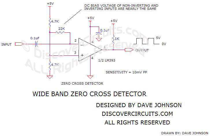
We have to be careful not to use any pre-amplifiers since they will add more slew to the signal.

Matt Watts

Re: VIC v5 driver board order list
« Reply #121, on June 12th, 2018, 12:17 PM »
Quick test with two frequencies (180Hz, 440Hz) and it looks like I can track the zero cross fairly well.  Will have to do more testing at higher frequencies.

Left scope-shots are with signal rising through zero; right scope-shots are dropping through zero.

Top shots are @ 180Hz; bottom @ 440Hz.

So the logic needed for the left signals is to invert and trigger a set.  On the right, just trigger the reset.

Matt Watts

Re: VIC v5 driver board order list
« Reply #122, on June 12th, 2018, 09:11 PM »Last edited on June 12th, 2018, 09:14 PM
Play it again Sam...

So with this circuit and the input level kept reasonably low, pretty good performance can be achieved.  Problem I see now is noise, easily detectible on the scope trigger.  Adding some hysteresis takes out the noise, but adds serious phase lag.  Just can't win for losing.   :sad:


Matt Watts

Current Flow Indicator
« Reply #124, on June 13th, 2018, 10:40 AM »
Quote from securesupplies on June 13th, 2018, 07:38 AM
nice
Not so much.  We're doing this wrong.  We don't want zero cross detection.  What we want is a current flow direction indication, this will put us in a phase aligned mode between the energy we inject into the VIC and the energy already flowing in the tank circuit.  If we do this, the PLL will no longer fight to phase align itself to achieve proper resonance--jitter will stop and lock can be easily obtained.

Replacing the zero-cross detection with current flow indication will be a little tricky and will require isolation.  We will need to remove the current sense transformer and replace it with a low value current sense resistor.  Across this resister we can place the two leads of the differential comparator.  We need to power the comparator with an isolated DC to DC converter since we have no common ground anymore.  The comparator will then illuminate the LED of an optical isolator when current is flowing in the "forward" direction and extinguish it when current is flowing in the "backwards" direction.  Forward and backwards is related to the direction of our signal injection to the VIC.  The output of the optical isolator then connects to the signal input of the PLL.

Below is a scope shot of the PLL trying to fight its way into resonance--which it is unable to accomplish.  Resonant lock should be at 180Hz.  The PLL starts out at 45Hz and climbs right past the resonant frequency.  Notice on this scope shot what the PLL is attempting to do.  When the yellow injection signal is high, the purple sine wave is transitioning from low to high; signal off when the sine wave is transitioning low.  This is what the PLL is designed to align on.  We need to feed the PLL the same kind of signal input from the feedback.  It's unfortunate my scope isn't capable of recording a short video of this process, because it's clear as day what is happening.