VIC v5 driver board order list
Per se
nav
Re: VIC v5 driver board order list
« Reply #127, on June 13th, 2018, 03:30 PM »Last edited on June 13th, 2018, 03:35 PM
Matt, the PLL on the CCFL circuit is through the ground state current potential which inputs the chip. On Stan's Vic this circuit cannot be applied because of the high voltage potential on both the positive and negative chokes hence the use of the pickup coil. BUT....what you can do Matt is to make the negative choke bifilar, tune the isolated half of the bifilar, the pickup coil and a capacitor to the same resonance as the VIC and cell then use the isolated pickup circuit to PLL the current into the control chip of the VIC.
Reading through some of that doc,
it is possible that we use a h bridge as the gate or in conjunction,
so h bridge logic is the pwm in and then electron extract on offer time,
this would for a moment isolate the step charge and capacitance compounding voltage ringing in circuit
and measurement could occur at moment it re in gauges, as it would be fluxing
it is a amazing circuit for sure.
You guy are more than qualified to comment on this as a option , I have seen several attempt to do this with h bridges
Petlov and others.
Dan
securesupplies
Re: VIC v5 driver board order list
« Reply #129, on June 13th, 2018, 07:38 PM »Last edited on June 13th, 2018, 07:44 PM
in the pdf doc Matt linked to
120 Bidirectional Current Sensing in H-Bridge Drivers Page 29
121 Single Output Provides 10A H-Bridge Current and Direction Page
Indexed Page 13
120 Bidirectional Current Sensing in H-Bridge Drivers Page 29
121 Single Output Provides 10A H-Bridge Current and Direction Page
Indexed Page 13
Matt Watts
Re: VIC v5 driver board order list
« Reply #130, on June 13th, 2018, 08:27 PM »Last edited on June 13th, 2018, 08:32 PM
Guys, we are not after natural resonance here. We are after parametric resonance. But to get there we must be able to achieve basic resonance first, practically with our eyes closed. We don't need 10 amp h-bridges and all that crap. We need a simple precision, low power stimulation, then we turn on the parametric switching and the system takes care of itself as long as we can continue to track the proper frequency. As Dr. Butikov stated, the amplitude will be exponential gains per cycle--step charging on steroids. We do this correctly and you'll have more Hydroxy gas than you'll ever imagine.
Russ has explained how you find the resonant frequency in a tank circuit; the ring test is the easiest. Once you find that, you must have a driver system that can find it too, with the flip of switch. The PLL should go right to that same frequency and hold the frequency there without jitter. Get this right, then you can do the parametric switching. That's my goal and I'll figure out a way to do it and share it as I go along.
Russ has explained how you find the resonant frequency in a tank circuit; the ring test is the easiest. Once you find that, you must have a driver system that can find it too, with the flip of switch. The PLL should go right to that same frequency and hold the frequency there without jitter. Get this right, then you can do the parametric switching. That's my goal and I'll figure out a way to do it and share it as I go along.
Cycle
Re: VIC v5 driver board order list
« Reply #131, on June 13th, 2018, 09:09 PM »Last edited on June 13th, 2018, 09:12 PM by Cycle
Play it again Sam...
So with this circuit and the input level kept reasonably low, pretty good performance can be achieved. Problem I see now is noise, easily detectible on the scope trigger. Adding some hysteresis takes out the noise, but adds serious phase lag. Just can't win for losing. :sad:
A “Bias Frame” is a zero-length (dark) exposure intended to measure just the difference between the pixels (the bias) and any additional noise added during the process of reading the image from the CCD and converting it into a digital image file. Because the CCD pixels are emptied immediately before the image is read from the CCD, only a small amount of dark current has had a chance to build up, but that rate of accumulation varies slightly for every pixel. Also, reading an image from a CCD is not instantaneous. Pixels near the bottom of the CCD are read later than pixels closer to the top of the CCD so pixels toward the bottom tend to have slightly higher pixel values than pixels closer to the top.
Cycle
Re: VIC v5 driver board order list
« Reply #132, on June 13th, 2018, 09:19 PM »Last edited on June 13th, 2018, 09:25 PM by Cycle
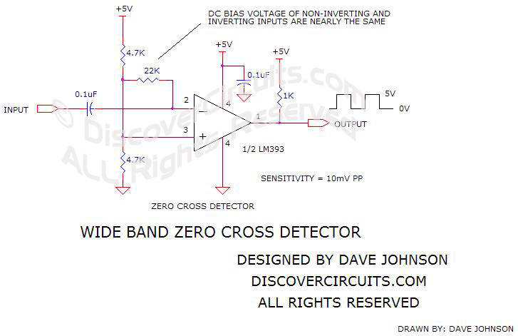
Not so much. We're doing this wrong. We don't want zero cross detection. What we want is a current flow direction indication, this will put us in a phase aligned mode between the energy we inject into the VIC and the energy already flowing in the tank circuit. If we do this, the PLL will no longer fight to phase align itself to achieve proper resonance--jitter will stop and lock can be easily obtained.
The peak of the waveform (either positive or negative) denotes a change in direction of current flow.
Perhaps a diode and capacitor for each half of the waveform. The diode will conduct in only one direction, to charge the (very small) capacitor to the peak voltage of the waveform.
Now have a comparator which compares the waveform voltage to the capacitor voltage on each side of the waveform.
When the comparator sees the waveform voltage (positive) is equal to Capacitor1 voltage (high), it knows voltage has peaked and is reversing (and will start falling).
When the comparator sees the waveform voltage (negative) is equal to Capacitor2 voltage (low), it knows voltage has peaked (bottomed) and is reversing (and will start rising).
Matt Watts
Sine Rise to Square
« Reply #133, on June 14th, 2018, 01:27 AM »Last edited on June 14th, 2018, 01:50 AM
Rock-n-Roll ! Though the slew rate is a tad slow, but good enough for these frequencies.Quote from Cycle on June 13th, 2018, 09:19 PM Similar. The rising edge is the bottom peak and the falling edge is the top peak.
Now we have a current flow direction indication that we can pipe into the PLL. When the signal is high, current is flowing forward and when low, the current is flowing in the reverse direction. This gives us the phase alignment missing from the original design.
Now to add the optical isolation...
So essentially what you want is a waveform peak detector, right?
Now we have a current flow direction indication that we can pipe into the PLL. When the signal is high, current is flowing forward and when low, the current is flowing in the reverse direction. This gives us the phase alignment missing from the original design.
Now to add the optical isolation...
securesupplies
Re: VIC v5 driver board order list
« Reply #134, on June 15th, 2018, 11:04 PM »Last edited on June 16th, 2018, 01:45 AM
I am posting this for the simple review
and thought as you move forward ,
it seams to have a few things going on comment positive and negative on this may help advance forward. for selecting the mechanism for pll.
1 is from Tony Wood side simply drawing vic
other anonymous Acid Bite from builder group.
We have to keep in mind a way to extract electron during
the gate it is rather important to have that timed ability. ( making load during gate to extract electrons)
H bridge logic is one way forward reverse
Matt is at a very high level on this work and can see the current draws in his mind better than most as he designed circuit,
I just post for careful thought so we keep the electron extract timing as a option as we do it as the increase in energy density
of h2 to h1 by removing electrons during gate is what gives us the end performance of gas we release.
Which is vital to keep in mind to honor the Meyers system.
NOTE "
It is nescessary in the final electron extraction ,
that the frequency with whch electrons are rrmoved from the system be
sequenced and synchronized with the circuit with the pulsing resonant cavity"
Dan
There may end up being a version 6 driver board, but it will probably turn out to be far more universal and not strictly for the VIC. Likely will be a universal parametric resonance board that can be used for all sorts of things, even a Tesla earthquake machine. ;-)
securesupplies
Re: VIC v5 driver board order list
« Reply #136, on June 16th, 2018, 01:45 AM »Last edited on June 16th, 2018, 01:53 AM
added image above
If transistor is not on the vic 5
I see no reason why there can not be a transistor Daughter board with similar concept
if you know how to draw this with 2 alternating transistors syncing to gate please post drawing
is beyond my brain today reading. that would be cool as it would make a electron extractions daughter board based on transistors
I attached this one to advance and keep it in mind. as you progress.
Impressive Work Matt ,
not sure about earth quake machines you have too many dam in Co lol
Dan
Impressive Work Matt ,
not sure about earth quake machines you have too many dam in Co lol
Cycle
Re: VIC v5 driver board order list
« Reply #138, on June 16th, 2018, 11:56 AM »Last edited on June 16th, 2018, 12:09 PM by Cycle
Rock-n-Roll ! Though the slew rate is a tad slow, but good enough for these frequencies.Similar. The rising edge is the bottom peak and the falling edge is the top peak.Quote from Cycle on June 13th, 2018, 09:19 PM So essentially what you want is a waveform peak detector, right?
Now we have a current flow direction indication that we can pipe into the PLL. When the signal is high, current is flowing forward and when low, the current is flowing in the reverse direction. This gives us the phase alignment missing from the original design.
Now to add the optical isolation...
The lower the resistance, the lower the voltage on the cap, so it'll cause the peak detector to lead the waveform by an amount proportional to the inverse of the resistance. You might exploit this by using variable resistance so you can change the lead time of the peak detector (in the analogy of the kid on a swing, it's somewhat akin to 'catching' the swing before it reaches its apex, and starting to push on it before that apex).
Matt Watts
Re: VIC v5 driver board order list
« Reply #139, on June 17th, 2018, 10:43 PM »Last edited on June 17th, 2018, 10:51 PM
There's a much easier way to do this, completely passive mind you and with a component I'm sure everyone already has.
Here's a hint:

If you look closely, you'll see them in use:
https://www.youtube.com/watch?v=6j860XSP2fU
https://www.youtube.com/watch?v=GmlpV1MWm40
Here's a hint:

If you look closely, you'll see them in use:
https://www.youtube.com/watch?v=6j860XSP2fU
https://www.youtube.com/watch?v=GmlpV1MWm40
HMS-776
Re: VIC v5 driver board order list
« Reply #140, on July 25th, 2018, 08:22 AM »Last edited on July 25th, 2018, 08:25 AM
I'm going to get back into the WFC stuff within the next few months. Last year I made this driver circuit on the breadboard.
https://youtu.be/ZSqPHSNrILM
This circuit provides a synchronized gate and drive frequency to prevent the last pulse before the gate from being cut short, it also gives me adjustable gate & drive duty, offset voltage and variable amplitude pulsing during the gate time (see 1:20 in the video).
Got some machining work to do soon, will have a new video describing it when the machining is done.
Webmug
Re: VIC v5 driver board order list
« Reply #141, on July 25th, 2018, 08:48 AM »Last edited on July 27th, 2018, 05:04 AM
I'm going to get back into the WFC stuff within the next few months. Last year I made this driver circuit on the breadboard.
https://youtu.be/ZSqPHSNrILM
This circuit provides a synchronized gate and drive frequency to prevent the last pulse before the gate from being cut short, it also gives me adjustable gate & drive duty, offset voltage and variable amplitude pulsing during the gate time (see 1:20 in the video).
Got some machining work to do soon, will have a new video describing it when the machining is done.
Its been a while since I posted on rwg. I have a few questions about your circuit: can it do automatic resonance tuning as well and were can we find the circuit?
~webmug
It can't do automatic tuning. I personally have tried several PLL oscillators and haven't had luck with any of them.
Circuit is just on a breadboard right now and in storage. I'm planning on getting it all out again soon. Once I do I'll make a schematic.
cool
Gunther Rattay
Re: VIC v5 driver board order list
« Reply #144, on September 8th, 2019, 11:48 AM »Last edited on September 8th, 2019, 01:34 PM
Guys, we are not after natural resonance here. We are after parametric resonance. But to get there we must be able to achieve basic resonance first, practically with our eyes closed. We don't need 10 amp h-bridges and all that crap. We need a simple precision, low power stimulation, then we turn on the parametric switching and the system takes care of itself as long as we can continue to track the proper frequency. As Dr. Butikov stated, the amplitude will be exponential gains per cycle--step charging on steroids. We do this correctly and you'll have more Hydroxy gas than you'll ever imagine.
Russ has explained how you find the resonant frequency in a tank circuit; the ring test is the easiest. Once you find that, you must have a driver system that can find it too, with the flip of switch. The PLL should go right to that same frequency and hold the frequency there without jitter. Get this right, then you can do the parametric switching. That's my goal and I'll figure out a way to do it and share it as I go along.
With my PGen 2.0 I have pll to find forced/natural resonance at 90° phase shift or any other angle I want to have. And I have square wave pulses thru a driver circuit.
Thru timing calculations I can easily switch over from natural to parametric resonance without extensive hardware in my circuit design. But what is the load configuration? inductance or capacitance must be made variable.
I have to understand paper´s calculations (not yet) to get correct phase shift for my square wave signal ...
In Stan´s WFC configuration of course the water capacitor is the variable part. capacitance and resistance change depending on water excitation state.
feedback coil phase shift will give information about derivation from natural resonance frequency but how to add in the parametric excitation component?
is there a dependency between natural resonance frequency and parametric resonance excitation frequency?
For the WFC a single pulse will be overdampened so that that half wave will immediately stop without swinging to the opposite...
But if inductance is large enough ... ?!?