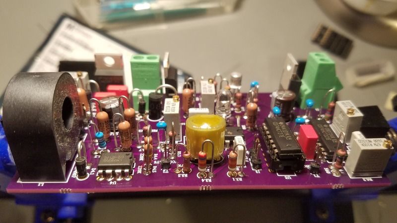
Yes, I did somehow forget the 15k resistor, but I thought I updated the BOM since then. My mistake. Perfection is what I strive for, not what I am. :D
Henne, your 5 volt regulator is in backwards. Don't put power to that board until you fix it.
There's also a line drawn on the board near R3.6 & R3.7, you'll need to solder a piece of lead in there. And you are missing a 120 ohm resistor at R2.2. It also looks like your LED may be backwards too. Other than those things and C3.3 being a different footprint, it looks pretty good.
Set your current limit way down to something like 5 mA and give it a shot after you fix the few booboos. You should be good to go. Then follow my video to get the basic tuning points set.
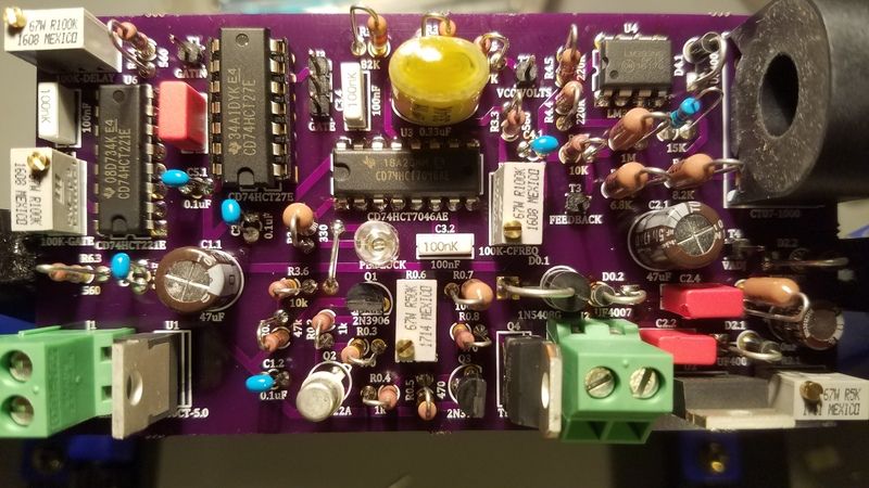
Attached is a tight high-res image of my board you can compare against.
You'll notice the diodes and resistors being axial components, not radial, are mounted vertical to save space. There is also a trick to this and I do it for another reason not obvious. The body side goes to the hole with the circle around it and the lead end goes to the other hole. For diodes, the strip (cathode) points upward. For resistors, one would say it doesn't matter since they are not polarized. That would be correct, however I have them placed the way I do because the top side you may want to connect a scope probe to for diagnostics.
Also on the pots, they can be soldered in either way, but if you align pin #1, the turn direction will all be consistent--clockwise higher, counter-clockwise lower. At least that was my plan when I designed it.
The bottom of the board is a ground plane, so if you look at the bottom and notice if the pin has a contact there to the ground plane, that will help you with the polarity orientation. I had to do this with the LED because I could not see well enough--I'm using a smaller one than in the BOM. I also used tantalums for the filter caps and they are polarized like electrolytics.

