Step by step VIC build

enrev

RE: Step by step VIC build
« Reply #400, on January 26th, 2013, 03:23 AM »
Quote from DanB on January 25th, 2013, 03:04 PM
Bifilar is when you wind two wires in the same bobin cavity, in the same direction, they are side by side and not arbitrarily wound. There is two ways to wire the two coils, aiding or opposing, the magnetic fields can add to one another or subtract. If you wire then opposing, what you get is a non inductive resistance. Wire them in aiding, you will get more inductance than both because of the mutual inductace between the two coils.

You can not have one coil of a bifilar coil variable. If Stan had a variable coil in the negative side of the circuit, these coils were not bifilar wound. Most likely seperate coils. This is not to say they are not on the same magnetic core. You could have one along side the other on a ferite rod, one having a wiper arm.

It is unclear how the bifilar coils react when there is a cell in between them. The timing of the bifilar coils magnetic fields could cause some type of modulation and even thou they are wired opposing, because the fields are not the same or not at the same time, this may cause some other effect we are looking for. Stan seems to always have coils in the positive and negative sides of the cell. They also seems to always be magneticlly connected.
I'm fine with all what you said. Let's forget bifilar as it creates misunderstanding; my point is that in Stan's design L1 and L2 are always wounded in opposite directions and magnetically coupled and there is a clear reason for doing that, it's not a mistake in the patent's picture. The bifilar is just a particular way of crancking the 2 inductances because as you have noticed the way the bifilar are connected is creating 2 opposite magnetic fields, same behaviour you get with two regular coils wounded in opposite directions.
What we need to concentrate on is the diode; it opens the circuit after the initial charge of the capacitor therefore the system can only work if it is properly magnetically coupled otherwise there is no way to transfer energy from the transformer/supply to the wfc (the diode prevents that).
My conclusion is that if you put a diode but your vic transformer is not properly magnetically coupled the system cannot work and it's not a matter of tuning the parameters. This is why I'm asking how the vic transformer is being wounded by the forum friends having troubles to find resonance.
On the other side if you remove the diode the system can work but not very efficiently as there is energy flowing back from the LC to the tranformer prime. The principle is the same that happens in the tesla coil when the sparking gap closes the circuit too long because of air ionizzation. Both Dave Lawton and Ravi's replica of the wfc were working but way less efficient then Stan's one and guess what... they didn't have the diode. Also the original wfc, the one from which clearly Stan got inspired from Puharich didn't have the diode while everything else was almost the same...a part the words used by the inventors to explain their works.
Back to my question: how do you explain the way the diode works in the vic circuit? I haven't found any good explanation so far.

Jul.

Matt Watts

RE: Step by step VIC build
« Reply #401, on January 26th, 2013, 11:48 AM »Last edited on January 26th, 2013, 12:07 PM by Matt Watts
Quote from enrev on January 26th, 2013, 03:23 AM
Back to my question: how do you explain the way the diode works in the vic circuit? I haven't found any good explanation so far.
The only obvious characteristic I can see is you are no longer dealing with an AC circuit, but instead a pulsed DC circuit.  And having the inductors magnetically coupled in a pulsed DC circuit gives you a hybrid design which is difficult to find good examples/explanations.  Even Wikipedia's reference is very weak.

https://en.wikipedia.org/wiki/Pulsed_DC


I'm afraid we are pretty much on our own unless we are able to break the individual components down to their purpose and how they interact with the other components.  Possibly using the Superposition Theorem may help:
https://en.wikipedia.org/wiki/Superposition_theorem
http://www.allaboutcircuits.com/vol_1/chpt_10/7.html

One will still have to be very cautious of the magnetic coupling, maybe even to the point of looking at the inductors as transformers.

gpssonar

RE: Step by step VIC build
« Reply #402, on January 26th, 2013, 01:04 PM »
Quote from Dog-One on January 26th, 2013, 11:48 AM
Quote from enrev on January 26th, 2013, 03:23 AM
Back to my question: how do you explain the way the diode works in the vic circuit? I haven't found any good explanation so far.
The only obvious characteristic I can see is you are no longer dealing with an AC circuit, but instead a pulsed DC circuit.  And having the inductors magnetically coupled in a pulsed DC circuit gives you a hybrid design which is difficult to find good examples/explanations.  Even Wikipedia's reference is very weak.

https://en.wikipedia.org/wiki/Pulsed_DC


I'm afraid we are pretty much on our own unless we are able to break the individual components down to their purpose and how they interact with the other components.  Possibly using the Superposition Theorem may help:
https://en.wikipedia.org/wiki/Superposition_theorem
http://www.allaboutcircuits.com/vol_1/chpt_10/7.html

One will still have to be very cautious of the magnetic coupling, maybe even to the point of looking at the inductors as transformers.
Dog, That's the way i am looking at the inductors, as transformers right now in the pulse on, in the pulse off they act as inductors. Still doing testing.

geenee

RE: Step by step VIC build
« Reply #403, on January 26th, 2013, 02:21 PM »Last edited on January 26th, 2013, 02:32 PM by geenee
Quote from enrev on January 26th, 2013, 03:23 AM
Quote from DanB on January 25th, 2013, 03:04 PM
Bifilar is when you wind two wires in the same bobin cavity, in the same direction, they are side by side and not arbitrarily wound. There is two ways to wire the two coils, aiding or opposing, the magnetic fields can add to one another or subtract. If you wire then opposing, what you get is a non inductive resistance. Wire them in aiding, you will get more inductance than both because of the mutual inductace between the two coils.

You can not have one coil of a bifilar coil variable. If Stan had a variable coil in the negative side of the circuit, these coils were not bifilar wound. Most likely seperate coils. This is not to say they are not on the same magnetic core. You could have one along side the other on a ferite rod, one having a wiper arm.

It is unclear how the bifilar coils react when there is a cell in between them. The timing of the bifilar coils magnetic fields could cause some type of modulation and even thou they are wired opposing, because the fields are not the same or not at the same time, this may cause some other effect we are looking for. Stan seems to always have coils in the positive and negative sides of the cell. They also seems to always be magneticlly connected.
I'm fine with all what you said. Let's forget bifilar as it creates misunderstanding; my point is that in Stan's design L1 and L2 are always wounded in opposite directions and magnetically coupled and there is a clear reason for doing that, it's not a mistake in the patent's picture. The bifilar is just a particular way of crancking the 2 inductances because as you have noticed the way the bifilar are connected is creating 2 opposite magnetic fields, same behaviour you get with two regular coils wounded in opposite directions.
What we need to concentrate on is the diode; it opens the circuit after the initial charge of the capacitor therefore the system can only work if it is properly magnetically coupled otherwise there is no way to transfer energy from the transformer/supply to the wfc (the diode prevents that).
My conclusion is that if you put a diode but your vic transformer is not properly magnetically coupled the system cannot work and it's not a matter of tuning the parameters. This is why I'm asking how the vic transformer is being wounded by the forum friends having troubles to find resonance.
On the other side if you remove the diode the system can work but not very efficiently as there is energy flowing back from the LC to the tranformer prime. The principle is the same that happens in the tesla coil when the sparking gap closes the circuit too long because of air ionizzation. Both Dave Lawton and Ravi's replica of the wfc were working but way less efficient then Stan's one and guess what... they didn't have the diode. Also the original wfc, the one from which clearly Stan got inspired from Puharich didn't have the diode while everything else was almost the same...a part the words used by the inventors to explain their works.
Back to my question: how do you explain the way the diode works in the vic circuit? I haven't found any good explanation so far.

Jul.
this's a diode and choke and frequency doubling.he used step down transformer with center tap(60hz)to explain,with bifilar choke.i don't test yet if not use transformer with center tap, bifilar choke but use only 2 regular chokes on the same core and pulse transformer without center tap. video from Tonywoodside.


https://www.youtube.com/watch?v=tR0VOZMPjNg

thanks
geenee

Faisca

RE: Step by step VIC build
« Reply #404, on January 26th, 2013, 02:24 PM »Last edited on January 26th, 2013, 03:18 PM by Faisca
Quote from enrev on January 26th, 2013, 03:23 AM
Quote from DanB on January 25th, 2013, 03:04 PM
Bifilar is when you wind two wires in the same bobin cavity, in the same direction, they are side by side and not arbitrarily wound. There is two ways to wire the two coils, aiding or opposing, the magnetic fields can add to one another or subtract. If you wire then opposing, what you get is a non inductive resistance. Wire them in aiding, you will get more inductance than both because of the mutual inductace between the two coils.

You can not have one coil of a bifilar coil variable. If Stan had a variable coil in the negative side of the circuit, these coils were not bifilar wound. Most likely seperate coils. This is not to say they are not on the same magnetic core. You could have one along side the other on a ferite rod, one having a wiper arm.

It is unclear how the bifilar coils react when there is a cell in between them. The timing of the bifilar coils magnetic fields could cause some type of modulation and even thou they are wired opposing, because the fields are not the same or not at the same time, this may cause some other effect we are looking for. Stan seems to always have coils in the positive and negative sides of the cell. They also seems to always be magneticlly connected.
I'm fine with all what you said. Let's forget bifilar as it creates misunderstanding; my point is that in Stan's design L1 and L2 are always wounded in opposite directions and magnetically coupled and there is a clear reason for doing that, it's not a mistake in the patent's picture. The bifilar is just a particular way of crancking the 2 inductances because as you have noticed the way the bifilar are connected is creating 2 opposite magnetic fields, same behaviour you get with two regular coils wounded in opposite directions.
What we need to concentrate on is the diode; it opens the circuit after the initial charge of the capacitor therefore the system can only work if it is properly magnetically coupled otherwise there is no way to transfer energy from the transformer/supply to the wfc (the diode prevents that).
My conclusion is that if you put a diode but your vic transformer is not properly magnetically coupled the system cannot work and it's not a matter of tuning the parameters. This is why I'm asking how the vic transformer is being wounded by the forum friends having troubles to find resonance.
On the other side if you remove the diode the system can work but not very efficiently as there is energy flowing back from the LC to the tranformer prime. The principle is the same that happens in the tesla coil when the sparking gap closes the circuit too long because of air ionizzation. Both Dave Lawton and Ravi's replica of the wfc were working but way less efficient then Stan's one and guess what... they didn't have the diode. Also the original wfc, the one from which clearly Stan got inspired from Puharich didn't have the diode while everything else was almost the same...a part the words used by the inventors to explain their works.
Back to my question: how do you explain the way the diode works in the vic circuit? I haven't found any good explanation so far.

Jul.
Jul. this is not my line, but I'll put an idea to explain the diode, and the circuit "LC":
First, understand that the cell is not the capacitor is a resistor (Meyer's words). The capacitor "C" is created by bifilar.
Thus the diode is needed to insulate the tank "LC" of the pulse transformer. Now you see a lot of similarity with the patent of Puharich. You now have ac and resonance. Perhaps the imbalance of L1 and L2 helps cell to produce  H.
Quote from geenee on January 26th, 2013, 02:21 PM
Quote from enrev on January 26th, 2013, 03:23 AM
Quote from DanB on January 25th, 2013, 03:04 PM
Bifilar is when you wind two wires in the same bobin cavity, in the same direction, they are side by side and not arbitrarily wound. There is two ways to wire the two coils, aiding or opposing, the magnetic fields can add to one another or subtract. If you wire then opposing, what you get is a non inductive resistance. Wire them in aiding, you will get more inductance than both because of the mutual inductace between the two coils.

You can not have one coil of a bifilar coil variable. If Stan had a variable coil in the negative side of the circuit, these coils were not bifilar wound. Most likely seperate coils. This is not to say they are not on the same magnetic core. You could have one along side the other on a ferite rod, one having a wiper arm.

It is unclear how the bifilar coils react when there is a cell in between them. The timing of the bifilar coils magnetic fields could cause some type of modulation and even thou they are wired opposing, because the fields are not the same or not at the same time, this may cause some other effect we are looking for. Stan seems to always have coils in the positive and negative sides of the cell. They also seems to always be magneticlly connected.
I'm fine with all what you said. Let's forget bifilar as it creates misunderstanding; my point is that in Stan's design L1 and L2 are always wounded in opposite directions and magnetically coupled and there is a clear reason for doing that, it's not a mistake in the patent's picture. The bifilar is just a particular way of crancking the 2 inductances because as you have noticed the way the bifilar are connected is creating 2 opposite magnetic fields, same behaviour you get with two regular coils wounded in opposite directions.
What we need to concentrate on is the diode; it opens the circuit after the initial charge of the capacitor therefore the system can only work if it is properly magnetically coupled otherwise there is no way to transfer energy from the transformer/supply to the wfc (the diode prevents that).
My conclusion is that if you put a diode but your vic transformer is not properly magnetically coupled the system cannot work and it's not a matter of tuning the parameters. This is why I'm asking how the vic transformer is being wounded by the forum friends having troubles to find resonance.
On the other side if you remove the diode the system can work but not very efficiently as there is energy flowing back from the LC to the tranformer prime. The principle is the same that happens in the tesla coil when the sparking gap closes the circuit too long because of air ionizzation. Both Dave Lawton and Ravi's replica of the wfc were working but way less efficient then Stan's one and guess what... they didn't have the diode. Also the original wfc, the one from which clearly Stan got inspired from Puharich didn't have the diode while everything else was almost the same...a part the words used by the inventors to explain their works.
Back to my question: how do you explain the way the diode works in the vic circuit? I haven't found any good explanation so far.

Jul.
this's a diode and choke and frequency doubling.he used step down transformer with center tap(60hz)to explain,with bifilar choke.i don't test yet if not use transformer with center tap, bifilar choke but use only 2 regular chokes on the same core and pulse transformer without center tap. video from Tonywoodside.


https://www.youtube.com/watch?v=tR0VOZMPjNg

thanks
geenee
Please make for clarity in the diagram. Draw and shoot.
Note: A problem of this guidance, when I receive mail, to see the new post, I am directed to the first page. Someone else, does this happen?

Gunther Rattay

RE: Step by step VIC build
« Reply #405, on January 27th, 2013, 10:44 AM »Last edited on January 27th, 2013, 11:08 AM by bussi04
Quote from enrev on January 26th, 2013, 03:23 AM
I'm fine with all what you said. Let's forget bifilar as it creates misunderstanding; my point is that in Stan's design L1 and L2 are always wounded in opposite directions and magnetically coupled and there is a clear reason for doing that, it's not a mistake in the patent's picture. The bifilar is just a particular way of crancking the 2 inductances because as you have noticed the way the bifilar are connected is creating 2 opposite magnetic fields, same behaviour you get with two regular coils wounded in opposite directions.
What we need to concentrate on is the diode; it opens the circuit after the initial charge of the capacitor therefore the system can only work if it is properly magnetically coupled otherwise there is no way to transfer energy from the transformer/supply to the wfc (the diode prevents that).
My conclusion is that if you put a diode but your vic transformer is not properly magnetically coupled the system cannot work and it's not a matter of tuning the parameters. This is why I'm asking how the vic transformer is being wounded by the forum friends having troubles to find resonance.
On the other side if you remove the diode the system can work but not very efficiently as there is energy flowing back from the LC to the tranformer prime. The principle is the same that happens in the tesla coil when the sparking gap closes the circuit too long because of air ionizzation. Both Dave Lawton and Ravi's replica of the wfc were working but way less efficient then Stan's one and guess what... they didn't have the diode. Also the original wfc, the one from which clearly Stan got inspired from Puharich didn't have the diode while everything else was almost the same...a part the words used by the inventors to explain their works.
Back to my question: how do you explain the way the diode works in the vic circuit? I haven't found any good explanation so far.

Jul.
First of all I think we should define some circuit design looked at as a standard configuration.

that might be the one Meyer calls VIC with primary, sec, diode, upper inductor, wfc and lower inductor.

Let´s  take the diode as a non ideal switch.
A switch because it opens the circuit depending on primary pulse condition.
Non ideal because when secondary voltage potential changes and current is going to change direction there is a short period of time while avalanche current really flows thru the diode to backwards direction. that may have some influence kinda oscillation effect to the inductors. there is some hint in Meyer´s doc to use fast switching diodes.

let´s take the inductors L1 and L2 as main reasons for current suppression.
Depending on primary pulsing condition there is a magnetic field collaps condition and at that time period the inductors become voltage sources that influences current flow thru the LCL configuration. it should be mentioned that there is a single diode in the circuit and that the lower path of the circuit stays coupled to the transformer´s secondary spool.

And due to the bifilar windings there is lots of parasitic capacitance in the system giving room for parallel and serial LCR configurations and oscillations.

There is poor information about primary circuit specials. there is always be shown a rectangular input signal but maybe there is some more components for resonance support or impedance matching.

I appreciate the good work of gps and rav so far and once the basic calculations for the static system as a startup are done

next step should be a dynamic system calculation.

how?

IHMO there are 2 ways minimum:

using LTSpice simulation always observing that simulation behaviour is similar to measured behaviour

or

using advanced calculations as used by Maple or Mathcad.

in both cases there are ways to recalculate magnetic flux parameters into electrical parameters and that way build a dynamic model of the system.

the same way the WFC in a third step can be modelled both ways.


the circuit diagram for a VIC can be easily be done using LTSpice:


Paul Butcher

RE: Step by step VIC build
« Reply #406, on January 29th, 2013, 01:36 PM »
Has everyone seen what has been achieved on each of these 5 links?

https://www.youtube.com/watch?v=rsPHvz_SAWA&feature=related
http://www.globalkast.com/products.htm
http://www.stansdream.com/products.htm
http://www.stanleymeyerwebshop.com/

https://www.youtube.com/watch?v=iJUtW7lStCw&list=UUEGe7GasoADRNz6wfHM91sQ

Seems as though there are some good hydrogen yields being achieved at low amperage. Can anyone verify if these guys circuits/work is genuine?

Paul Butcher

Lynx

RE: Step by step VIC build
« Reply #407, on January 29th, 2013, 02:34 PM »
Quote from Paul Butcher on January 29th, 2013, 01:36 PM
Has everyone seen what has been achieved on each of these 5 links?

https://www.youtube.com/watch?v=rsPHvz_SAWA&feature=related
http://www.globalkast.com/products.htm
http://www.stansdream.com/products.htm
http://www.stanleymeyerwebshop.com/

https://www.youtube.com/watch?v=iJUtW7lStCw&list=UUEGe7GasoADRNz6wfHM91sQ

Seems as though there are some good hydrogen yields being achieved at low amperage. Can anyone verify if these guys circuits/work is genuine?

Paul Butcher
I'd love to see some independent testimonials on any of these.

Amsy

RE: Step by step VIC build
« Reply #408, on January 31st, 2013, 04:12 AM »Last edited on January 31st, 2013, 04:24 AM by Amsy
Quote from Webmug on December 4th, 2012, 07:51 AM
Yes there is 180° out of phase at the negative choke due the reverse connection to the WFC.

Measure the total inductance and capacitance of the series circuit (L1, WFC, L2) :idea: Not,  11.507Hz :exclamation:

Br,
Webmug
Hi Webmug,

it was not my aim in this post, to look at the hole system. BTW measuring the hole system you have to check: Main secondarys L and C, L1 and C1, WFC-C, L2 and C2 and the L and C of the Pickup coil.
 
My aim was to show, that the L1 and L2 itself is a parallel resonant circuit, and it will swing because of their own resonant frequency, this will rise the Z on the right frequency very high.
Quote from Lynx on December 4th, 2012, 08:13 AM
I really don't understand the ones insisting on photoshopping Stan's images to include an AC voltage
to the WFC as opposed to a pulsed DC voltage.
What possible purpose would that serve?
It is all described in the post.
The voltage which I painted is, that of two ACs generated by the parallel resonant circuit in the coils with their own C component. Because this pictures which meyer painted in the patent is not possible to generate with DC, and it is not possible to record such a wave over the WFC on one channel.


Faisca

RE: Step by step VIC build
« Reply #409, on February 1st, 2013, 10:35 AM »Last edited on February 1st, 2013, 10:56 AM by Faisca
only a test
Quote from geenee on January 26th, 2013, 02:21 PM
Quote from enrev on January 26th, 2013, 03:23 AM
Quote from DanB on January 25th, 2013, 03:04 PM
Bifilar is when you wind two wires in the same bobin cavity, in the same direction, they are side by side and not arbitrarily wound. There is two ways to wire the two coils, aiding or opposing, the magnetic fields can add to one another or subtract. If you wire then opposing, what you get is a non inductive resistance. Wire them in aiding, you will get more inductance than both because of the mutual inductace between the two coils.

You can not have one coil of a bifilar coil variable. If Stan had a variable coil in the negative side of the circuit, these coils were not bifilar wound. Most likely seperate coils. This is not to say they are not on the same magnetic core. You could have one along side the other on a ferite rod, one having a wiper arm.

It is unclear how the bifilar coils react when there is a cell in between them. The timing of the bifilar coils magnetic fields could cause some type of modulation and even thou they are wired opposing, because the fields are not the same or not at the same time, this may cause some other effect we are looking for. Stan seems to always have coils in the positive and negative sides of the cell. They also seems to always be magneticlly connected.
I'm fine with all what you said. Let's forget bifilar as it creates misunderstanding; my point is that in Stan's design L1 and L2 are always wounded in opposite directions and magnetically coupled and there is a clear reason for doing that, it's not a mistake in the patent's picture. The bifilar is just a particular way of crancking the 2 inductances because as you have noticed the way the bifilar are connected is creating 2 opposite magnetic fields, same behaviour you get with two regular coils wounded in opposite directions.
What we need to concentrate on is the diode; it opens the circuit after the initial charge of the capacitor therefore the system can only work if it is properly magnetically coupled otherwise there is no way to transfer energy from the transformer/supply to the wfc (the diode prevents that).
My conclusion is that if you put a diode but your vic transformer is not properly magnetically coupled the system cannot work and it's not a matter of tuning the parameters. This is why I'm asking how the vic transformer is being wounded by the forum friends having troubles to find resonance.
On the other side if you remove the diode the system can work but not very efficiently as there is energy flowing back from the LC to the tranformer prime. The principle is the same that happens in the tesla coil when the sparking gap closes the circuit too long because of air ionizzation. Both Dave Lawton and Ravi's replica of the wfc were working but way less efficient then Stan's one and guess what... they didn't have the diode. Also the original wfc, the one from which clearly Stan got inspired from Puharich didn't have the diode while everything else was almost the same...a part the words used by the inventors to explain their works.
Back to my question: how do you explain the way the diode works in the vic circuit? I haven't found any good explanation so far.

Jul.
this's a diode and choke and frequency doubling.he used step down transformer with center tap(60hz)to explain,with bifilar choke.i don't test yet if not use transformer with center tap, bifilar choke but use only 2 regular chokes on the same core and pulse transformer without center tap. video from Tonywoodside.


https://www.youtube.com/watch?v=tR0VOZMPjNg

thanks
geenee
test...someone else see this?

Matt Watts

RE: Step by step VIC build
« Reply #410, on February 1st, 2013, 12:24 PM »
Quote from geenee on January 26th, 2013, 02:21 PM
this's a diode and choke and frequency doubling.he used step down transformer with center tap(60hz)to explain,with bifilar choke.i don't test yet if not use transformer with center tap, bifilar choke but use only 2 regular chokes on the same core and pulse transformer without center tap. video from Tonywoodside.
[url]https://www.youtube.com/watch?v=tR0VOZMPjNg
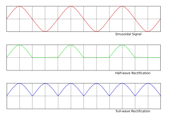
Keep in mind that using a center-tapped transformer is just like using a full wave bridge rectifier.  So in essence, having two chokes on the same core, depending upon how you hook-up your wiring, you have a center-tapped transformer.  So I would expect frequency doubling same as you would get from a full wave bridge rectifier.  Nothing too exciting about that.

Now if you have half wave rectification from just a single diode, you can build a snubber network that will in-effect, recreate the missing pulses and again, you will have frequency doubling.

Lynx

RE: Step by step VIC build
« Reply #411, on February 1st, 2013, 01:19 PM »
Quote from Dog-One on February 1st, 2013, 12:24 PM
Now if you have half wave rectification from just a single diode, you can build a snubber network that will in-effect, recreate the missing pulses and again, you will have frequency doubling.
A link please?
Thanks.

Matt Watts

RE: Step by step VIC build
« Reply #412, on February 1st, 2013, 05:16 PM »
Quote from Lynx on February 1st, 2013, 01:19 PM
Quote from Dog-One on February 1st, 2013, 12:24 PM
Now if you have half wave rectification from just a single diode, you can build a snubber network that will in-effect, recreate the missing pulses and again, you will have frequency doubling.
A link please?
Thanks.
http://www.snubberdesign.com/rcld-snubber-circuit-design-video.html

https://www.youtube.com/watch?v=sb4yiW7MFWM

The idea is to take the parasitic oscillations and damping them in such a way as to fill the missing pulse with the output of the snubber network.

http://www.digplanet.com/wiki/Snubber

HTH

Lynx

RE: Step by step VIC build
« Reply #413, on February 2nd, 2013, 02:33 AM »
Quote from Dog-One on February 1st, 2013, 05:16 PM
Quote from Lynx on February 1st, 2013, 01:19 PM
Quote from Dog-One on February 1st, 2013, 12:24 PM
Now if you have half wave rectification from just a single diode, you can build a snubber network that will in-effect, recreate the missing pulses and again, you will have frequency doubling.
A link please?
Thanks.
The idea is to take the parasitic oscillations and damping them in such a way as to fill the missing pulse with the output of the snubber network.
Ok, thanks.
I tried searching for this but all I can find is how to prevent parasitic oscillations
as oppsed to having them, as you say, doubling the frequency.
You wouldn't happen to have a link to such a simple most basic R/L/C/Diode schematic?
Sorry for asking but I'd love to see such a frequency doubling schematic that which
uses only one diode.

Faisca

RE: Step by step VIC build
« Reply #414, on February 2nd, 2013, 07:44 AM »
Back to my question: how do you explain the way the diode works in the vic circuit? I haven't found any good explanation so far.

Jul.[/quote]View photos and follow my reasoning:
1st - simplified diagram of Meyer.
2nd - hidden details: distributed capacitance between L1 and L2 and resistance of the cell.
3rd - simplified equivalent circuit "LCR" and rightly diode to isolate the source of pulses.
Someone argues that?

geenee

RE: Step by step VIC build
« Reply #415, on February 2nd, 2013, 07:34 PM »Last edited on February 2nd, 2013, 09:37 PM by geenee
i back to read birth of new tech book again,i found good things in wfc hydrogen gas management system.

about delrin, constant voltage across cell, pulse frequency, gate frequency, resonant of water molecule, longitudinal wave ,resonant action, ionization ,insulated housing ... etc. i never read it clearly,fast read and not interesting cause that is advance(i just need to know a basic).we must read it again!!!!

- about electrostatic filter assembly unit(440,figure 3-45)=purify water to delrin wfc.notice that pure water only to process resonant action in resonant cavity. read in section;Impurity Extraction Process!!!!!

---------------------------------
to Faisca,
diagram for only 8xa,9xb circuit??vic 5 coils don't have bifilar cause low capacitance???


thanks
geenee

Faisca

RE: Step by step VIC build
« Reply #416, on February 3rd, 2013, 11:04 AM »
Quote from geenee on February 2nd, 2013, 07:34 PM
i back to read birth of new tech book again,i found good things in wfc hydrogen gas management system.

about delrin, constant voltage across cell, pulse frequency, gate frequency, resonant of water molecule, longitudinal wave ,resonant action, ionization ,insulated housing ... etc. i never read it clearly,fast read and not interesting cause that is advance(i just need to know a basic).we must read it again!!!!

- about electrostatic filter assembly unit(440,figure 3-45)=purify water to delrin wfc.notice that pure water only to process resonant action in resonant cavity. read in section;Impurity Extraction Process!!!!!

---------------------------------
to Faisca,
diagram for only 8xa,9xb circuit??vic 5 coils don't have bifilar cause low capacitance???


thanks
geenee
Geenee you are right about the V.I.C. 5 reels, however nothing seems further away than ever Meyer said: "bifilar winding" which aliais was an invention of Tesla.
This V.I.C. 5 reels, many of us replicate without success, I see no chance of working, it is just a transformer, low income, with three secondaries connected in series with a diode, one of the secondary (called the choke) is turned upside down, the what does that cancel was induced in the other, then leaving only the product of a single secondary. It makes no sense, seems intentional disinformation.

CaptainKirk

RE: Step by step VIC build
« Reply #417, on February 19th, 2013, 12:24 AM »Last edited on February 19th, 2013, 12:40 AM by CaptainKirk
From: What is the diode doing there?

I too have issues with the diode in a resonant circuit.  I cannot get resonance in a simulator with it, unless I use a Zener Diode, and then I wonder if we are looking for a diode with a 20MV rating?

But, the diagram reminds me of this: Flyback Converter

I am also interested in 3 other issues brought up recently:

1) Coating the the tubes to add some insulation, maybe reduce the speed at which current can be passed.  
I WILL test this by next week.  I intend to get some paraffin wax heat it on the grill and drop my tubes into it.
(Just for one of my tubes), I will then COMPARE the output to my other tubes using the same voltage/current (just frequency driven)

2) Is it a capacitor or a resistor?  Interesting.  Considering it pushed current back after I turned off an unprotected power amplifier, and ruined the amplifier, I would say it most definitely acts like a capacitor.  But it might be worth thinking through that side of it a bit more.  (My next point)

3) The inductors can easily overwhelm the capacitor.  When it does, no current flows.  I get *nothing*.  Right now, I have a 10:1 transformer, and if I hook it up, it powers a light, and gives me 106V from 12V square pulsing.  But the minute I put a single tube on this thing.  I get nothing.  There is barely enough power to light the light (which I kept there one time).  And that reminded me, everything on the secondary side of a transformer MUST DRAW current or you get none.  That capacitor acts like an OPEN circuit until it charges and at low frequencies.  At high frequencies it acts like a short.  I have MANY tests confirming this.  The higher the frequency, the greater the current draw (without a vic).

If I use a hand made 0.352mH inductor.  I get a noticeable drop in current draw.  And I can scope the results a bit, and I know when I am going to start drawing current.  And that is when the inductor is overwhelmed by the frequency and the capacitor is now controlling the draw of current by being a short.  I am able to produce HHO at these restricted values (13.8V driving voltage, and pulling 0.65A  but it is FAIR production.  I wish I had a way to quantify.  (Kinda the next stage for me).

So, I repeat what Russ is saying.  Don't give up.  Others point out that we are learning and understanding.  Lets certainly see if we can break off some groups to test some thesis.  I believe that the inductors being used are way to large for the size of the capacitors (of course EVERYONES got different capacitors).  And I have had NO LUCK pushing 12V @ 3 AMPS  through a 10:1 transformer and making any bubbles (the MOSFET got hot!)...  Assuming I had 120V @ .3 Amps, I would have guessed that it would have worked.  I let it run until the FET got hot.  I was getting a LOT of inductance pushback (impedance).

HTH,

Kirk Out!


Quote from Faisca on February 3rd, 2013, 11:04 AM
Quote from geenee on February 2nd, 2013, 07:34 PM
i back to read birth of new tech book again,i found good things in wfc hydrogen gas management system.

about delrin, constant voltage across cell, pulse frequency, gate frequency, resonant of water molecule, longitudinal wave ,resonant action, ionization ,insulated housing ... etc. i never read it clearly,fast read and not interesting cause that is advance(i just need to know a basic).we must read it again!!!!

- about electrostatic filter assembly unit(440,figure 3-45)=purify water to delrin wfc.notice that pure water only to process resonant action in resonant cavity. read in section;Impurity Extraction Process!!!!!

---------------------------------
to Faisca,
diagram for only 8xa,9xb circuit??vic 5 coils don't have bifilar cause low capacitance???


thanks
geenee
Geenee you are right about the V.I.C. 5 reels, however nothing seems further away than ever Meyer said: "bifilar winding" which aliais was an invention of Tesla.
This V.I.C. 5 reels, many of us replicate without success, I see no chance of working, it is just a transformer, low income, with three secondaries connected in series with a diode, one of the secondary (called the choke) is turned upside down, the what does that cancel was induced in the other, then leaving only the product of a single secondary. It makes no sense, seems intentional disinformation.
Faisca,
  Agreed there is something fishy here, but not sure what.  Here are some observations.
1) We use the VIC and the B+ and B- are wired to make it a 30:1 step up transformer, but with B- and B+ Supposedly being 180 degrees out of phase.  Tony did a video, see this

Tony Explaining WaveForm from the VIC
But my concern is where he drew in the ZERO line.  Something is wrong.  These should be Positive Pulses, not AC Sine Waves.  Although an Inductor will do that the a positive pulse, but it does not always take it to +/- the same values (Zero can be below the wave since it is DC).

2) Why work so hard stepping up the voltage if it is RESONANCE at work????  (If we can take the 300V and step it up to 3KV and 3MV even, why are we working so hard to step up 12V to 300V?)  Is this to overcome the diode?  Or is the circuit designed like a Tesla Coil or Flyback Converter, where we need to have the ENTIRE circuit have its own LOOP of wire to operate in.

  I feel we are getting very close.  I always thought that Stan discovered a way to cause Dielectric Breakdown by overwhelming the medium with a very large E-Field.
Breakzeitgeist

RE: Step by step VIC build
« Reply #418, on February 23rd, 2013, 02:08 AM »


Ok.....Think like Stan maybe stan knew Tesla work well and if I were stan and I made a discovery and wanted to keep it from getting stolen like Tesla and his radio patent how would I do it?????? Also.....keep in mind that the most amazing things.... circuits whatever are always simple like everything in the universe. I think there is a very simple answer to all this....what facts do we have about what we want? I only seen Stan buggy run for real real with to many witnesses to be fake....News vid, you all seen it....see it 1 more time...you will see the alternator and a motor right behind stan on buggy at the end of vid.....sorry his circuit will not auto tune to resonance like you would want but you can achieve this with alternator and motor ...resonant  rpm.....I think its named...however there is a circuit that can do this but its not stans or tesla...more on that soon....maybe your circuits are for another device coil?? hint... alternator:-)   maybe not rewind just  remove regulator and use your circuits to drive it....biggest one you can find:-) stan said at the beginning of his talks....180 degrees out of phase the electrolysis process  begins = the other way...lol... Look we can do this I believe in you all and myself. I am because we are.... see my channel to know me more:)  https://www.youtube.com/user/Breakzeitgeist/videos?view=0&flow=grid

adys15

RE: Step by step VIC build
« Reply #419, on May 20th, 2013, 01:40 AM »
Hy guys !i have a small video in Don's files anybody knows where the signal is coming from?

Faisca

RE: Step by step VIC build
« Reply #420, on May 20th, 2013, 01:14 PM »
Quote from adys15 on May 20th, 2013, 01:40 AM
Hy guys !i have a small video in Don's files anybody knows where the signal is coming from?
seems to be the patent, which Meyer used a variac, rectified (120Hz) and pulse high frequenci.

gpssonar

RE: Step by step VIC build
« Reply #421, on May 20th, 2013, 08:32 PM »
Quote from adys15 on May 20th, 2013, 01:40 AM
Hy guys !i have a small video in Don's files anybody knows where the signal is coming from?
I don't know where it came from, But i can poduce the same signal with the polarzation process box that i built like Stan's.


adys15

RE: Step by step VIC build
« Reply #422, on May 21st, 2013, 01:00 AM »
[/quote]I don't know where it came from, But i can poduce the same signal with the polarzation process box that i built like Stan's.[/quote]Thanks,i found in the epp folder but seem so clean to be the 8xa...You are using the 8xa? like in Tony skematic?did you get stepcharge?can i use a mosfet instead of that scr because i can find it.Cheers!

gpssonar

RE: Step by step VIC build
« Reply #423, on May 21st, 2013, 02:54 AM »
Quote from adys15 on May 21st, 2013, 01:00 AM
I don't know where it came from, But i can poduce the same signal with the polarzation process box that i built like Stan's.[/quote]Thanks,i found in the epp folder but seem so clean to be the 8xa...You are using the 8xa? like in Tony skematic?did you get stepcharge?can i use a mosfet instead of that scr because i can find it.Cheers![/quote]I'm useing the 9XA from Max Miller, I've used both SCR/2n3055 and got the same signal. That wave form, the first charges the coil, the next is the discharge to the cell.


adys15

RE: Step by step VIC build
« Reply #424, on May 21st, 2013, 03:06 AM »
[/quote]I'm useing the 9XA from Max Miller, I've used both SCR/2n3055 and got the same signal. That wave form, the first charges the coil, the next is the discharge to the cell.[/quote]Thanks,i am trying to use direct wall voltage so i need a powerfull swich...