Stan Meyer's Steam Resonator

Davy Oneness

Re: Stan Meyer's Steam Resonator
« Reply #50, on August 26th, 2015, 08:56 AM »Last edited on August 26th, 2015, 02:32 PM
If those are chokes, where did the 220ohm measurement come from? if measured from the "chokes" they must be wire wound power  resistors, because you can't find a choke like that with that high of resistance. The fuse is your power coming into the circuit, the chassis is ground, and those transistors don't have the collectors connected to the heat sinks internally, so heat sink pads not issue (metal mounting screws would be an issue too, so  nylon screws would be used because non-conductive). lastly, what you think is the cell output, looks like the primary center tap to me(either normal center tap or bucking coil center tap), and that rec bridge you think is connected to alternator is really the cell output. In his schematics he shows another switch on the HV positive side, but most likely the primary switching accomplishes the same kind of  signal on the secondary, from the primary "switching noise" which normally would be smoothed out with a capacitor on the output :                           (Kept It Simple, Stan) .

push pull converter

Transformerless Push-Pull

Class AB power amplifier. (P.S. We don't need to worry about "cross over" distortion with DC pulses!))


http://s12.postimg.org/5u6ucorf1/20150826_143648_1.jpg

Also note: If his memo's mention "amp restriction" than the primary most definitely bucking coil arrangement. But easy enough to test once you have it set up on your bench.

Davy Oneness

Re: Stan Meyer's Steam Resonator
« Reply #51, on August 26th, 2015, 11:59 AM »Last edited on August 26th, 2015, 01:30 PM
Quote from brettly on August 4th, 2014, 05:23 AM
and heres a pic of stans control unit showing steam resonator control board
( which appears identical to the resonant cavity control sections)...suggesting either it uses same pulse circuit for steam res as the resonant cavities ( hho tubes) or he just used the same control panel for steam res for convenience ( I would guess its using same pulse circuit as stans work was very clean/finished design).
Looking at this just now, and I now think what I was calling  the center tap, is really the feedback coil. The card has a "lock" LED for resonance just like the VIC, so would have same circuit for that part also.This makes more sense to me with the full "push pull" style driver .
 :cool:

Here is what I see now:


http://s18.postimg.org/nv5oaxccp/20150826_162943_1.jpg

Davy Oneness

Re: Stan Meyer's Steam Resonator
« Reply #52, on August 26th, 2015, 03:48 PM »Last edited on August 26th, 2015, 04:25 PM
Ok, based off of studying Stan's schematic for the VIC driver, this one I just drew up for the steam resonator should work quite nicely!
 :cool:


http://s29.postimg.org/mpuo24mx3/20150826_192207_1.jpg

Use a separate 10volt supply through a volt regulator to switch driver, don't use the same 12v driving the coil because a HV spike may fry a transistor in the amplifier's input. 

brettly

Re: Stan Meyer's Steam Resonator
« Reply #53, on August 27th, 2015, 01:00 AM »
thanks davey oneness for looking over the steam resonator, its my understanding that the 220ohmn value came from somenone who measured the 220ohmn on stans device shown in the pics. I cant remember who it was, but someone had access to what was left of stans estate though a fair bit got sold to a company ( not that long ago).
Thats amazing you can understand it, and actually give a circuit that will be testable.
There was one other issue: how it is connected to the water bath, from memory its different to the wfc stainless tubes, which just have inner/outer tube connections. I think the steam resonator had three connections ( someone else might chime in on that ?), I'm really not sure on that, but there was some discussion on how its connected to the water.
My electronics knowledge is not all that advanced, so very much appreciate your input to assist making steam resonator ( heater) circuit replicable.
So would you say the purpose of the circuit is rapid switching of direction of flow of electrons ( or in stans case rapid switching of the voltage polarity with low amp draw), would you think the circuit I was trying to reverse engineer ( with only basic electronics knowledge) is designed to rapidly heat water? Some had suggested this was merely a power supply and not involved in water heating?
I think you have made a large contribution to understanding this bit of meyers work.

freethisone

Re: Stan Meyer's Steam Resonator
« Reply #54, on August 27th, 2015, 02:24 AM »
Quote from Davy Oneness on August 26th, 2015, 03:48 PM
Ok, based off of studying Stan's schematic for the VIC driver, this one I just drew up for the steam resonator should work quite nicely!
 :cool:


http://s29.postimg.org/mpuo24mx3/20150826_192207_1.jpg

Use a separate 10volt supply through a volt regulator to switch driver, don't use the same 12v driving the coil because a HV spike may fry a transistor in the amplifier's input.
now some one has there smart hat on..

Davy Oneness

Re: Stan Meyer's Steam Resonator
« Reply #55, on August 27th, 2015, 08:09 AM »Last edited on August 27th, 2015, 10:44 AM
Quote from brettly on August 27th, 2015, 01:00 AM
There was one other issue: how it is connected to the water bath, from memory its different to the wfc stainless tubes, which just have inner/outer tube connections. I think the steam resonator had three connections ( someone else might chime in on that ?), I'm really not sure on that, but there was some discussion on how its connected to the water.
This is what Im seeing:


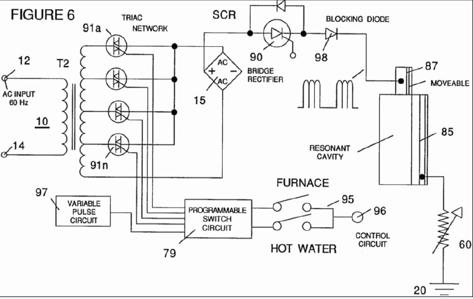
The triac network selects the higher through lower voltages from the secondary winding taps (your throttle control for heat), In this picture, the transformer is fed with 60hz AC, and the rectifier bridge turns that into HVDC, and then the SCR pulses it to the plates.
In the one I just reversed engineered, you can see the switching on the primary that the HV SCR would be doing, and the signal through the bridge rectifier would produce the same pulsing to the plates from what would be called "DC Ripple"
Lastly, the amp restriction in these was done by using stainless steal wire for the secondary (high resistance) looking at the secondary winding before, the way it is sectioned, the winding may reverse direction every little section to act like the bucking coil chokes on the VIC. BUT NOTE, the transformer from the estate we are using as ref, looks like plain old copper magnet wire!  It may also be possible to use a normal transformer with the bucking chokes set up at the plates like on the VIC.
Oh, and the dune buggy had a plastic water tank, so no case grounding. I think the case ground was for a dual plate, and this one I RE is an alternating single plate.

And one last thing, I don't think the signal is gated like on the VIC , it shows it in this picture, but was watching this video on using resonance to explode virus (like rife) and he specifically stated, that without a gating frequency the samples would just heat up and not explode.

Stan's control panels have no controls for adjusting duty cycles for ANY of the cards, in the same virus video, He said all the successful resonant shattering had one thing in common, the main freq was the 11th harmonic of the Gating frequency! So no need to adjust that, just tune the main freq, and the gate is automatically adjusted to harmonically match !

https://youtu.be/1w0_kazbb_U?t=7m5s

Davy Oneness

Re: Stan Meyer's Steam Resonator
« Reply #56, on August 27th, 2015, 08:29 AM »
Quote from Davy Oneness on August 26th, 2015, 03:48 PM
Ok, based off of studying Stan's schematic for the VIC driver, this one I just drew up for the steam resonator should work quite nicely!
 :cool:


http://s29.postimg.org/mpuo24mx3/20150826_192207_1.jpg

Use a separate 10volt supply through a volt regulator to switch driver, don't use the same 12v driving the coil because a HV spike may fry a transistor in the amplifier's input.
On second thought looking over this, I don't think R1 and R4 are used, and 470 ohm maybe best for R2 and R3

Davy Oneness

Re: Stan Meyer's Steam Resonator
« Reply #57, on August 27th, 2015, 09:26 AM »Last edited on August 27th, 2015, 09:42 AM
Stan using a pull down trigger to pulse the driver, is like having a loaded spring with a hair trigger release and a rapid recoil reset. As opposed to the way everyone has been trying to trigger all their FE circuits, which is more akin to kicking in the trigger with your foot and the primitive trigger mechanism drags across itself, and the spring, adding losses in its recoil speed and power output......then you can only go so fast, and when you do try doing it too fast, the whole operation gets unstable quickly........


Davy Oneness

Re: Stan Meyer's Steam Resonator
« Reply #59, on August 27th, 2015, 02:05 PM »
I understand now why the plates of the steam resonator are also stainless even though no hho is present. This is the same reason he uses stainless steal in his secondary windings, it is for the resistance!

"In a non-electrolytic capacitor and electrolytic capacitors with solid electrolyte the metallic resistance of the leads and electrodes and losses in the dielectric cause the ESR. "
Equivalent  series resistance (ESR)

Capacitors in electronics fail over time because the electrolyte (conductive part) dries up and the ESR goes up and it heats up (causing the ESR to go higher) from ripple currents hitting it (sound familiar?) until the gasses from the heat expand enough to explode the capacitor!


Matt Watts

Re: Stan Meyer's Steam Resonator
« Reply #60, on August 27th, 2015, 03:14 PM »
GPS, can you weigh-in on this thought.  I remember you saying resistance is critical.

Gunther Rattay

Re: Stan Meyer's Steam Resonator
« Reply #61, on August 28th, 2015, 10:49 AM »Last edited on August 28th, 2015, 10:53 AM
Quote from Davy Oneness on August 27th, 2015, 02:05 PM
I understand now why the plates of the steam resonator are also stainless even though no hho is present. This is the same reason he uses stainless steal in his secondary windings, it is for the resistance!

"In a non-electrolytic capacitor and electrolytic capacitors with solid electrolyte the metallic resistance of the leads and electrodes and losses in the dielectric cause the ESR. "
Equivalent  series resistance (ESR)

Capacitors in electronics fail over time because the electrolyte (conductive part) dries up and the ESR goes up and it heats up (causing the ESR to go higher) from ripple currents hitting it (sound familiar?) until the gasses from the heat expand enough to explode the capacitor!
What material should he have taken instead? Iron?

Esr is an effect that plays a role in capacitor lifetime of switched mode power supplies and  heat waste effects. Both don't play a role in steam resonator.

Davy Oneness

Re: Stan Meyer's Steam Resonator
« Reply #62, on August 28th, 2015, 03:47 PM »
Quote from Gunther Rattay on August 28th, 2015, 10:49 AM
What material should he have taken instead? Iron?

Esr is an effect that plays a role in capacitor lifetime of switched mode power supplies and  heat waste effects. Both don't play a role in steam resonator.
Really? "Esr is an effect that plays a role in capacitor" as "heat waste effects"? But no way it could "play a role in a steam resonator(capacitor)"??? OK, care to back up your opinion with something other than your opinion? or are you just here to waste my time?

Davy Oneness

Re: Stan Meyer's Steam Resonator
« Reply #63, on August 28th, 2015, 07:50 PM »
"The higher the ripple current, ESR, and thermal resistance
between the capacitor and ambient the higher the temperature
rise of the capacitor.   The temperature of the capacitor is di-
rectly  related  to  failure  rate—the  higher  the  temperature  of
operation the higher the predicted failure rate.  Ripple current
has no other detrimental effect on the capacitor beyond rais-
ing its core temperature"

http://www.newark.com/pdfs/techarticles/kemet/Ripple-Current-Capabilities-Technical-Update.pdf

Gunther Rattay

Re: Stan Meyer's Steam Resonator
« Reply #64, on August 29th, 2015, 12:06 AM »Last edited on August 29th, 2015, 12:20 AM
Quote from Davy Oneness on August 28th, 2015, 03:47 PM
Really? "Esr is an effect that plays a role in capacitor" as "heat waste effects"? But no way it could "play a role in a steam resonator(capacitor)"??? OK, care to back up your opinion with something other than your opinion? or are you just here to waste my time?
It´s obvious that everyone has ideas to tell about technical implementation of Stan Meyer system. But it´s important to differentiate between layman´s ideas and experience based ideas.

It´s no waste of time to set things straight for true researchers here ;)


Backup my opinion with facts? You´re welcome.

Make a short calculation for the tube sizes Stan Meyer used in his buggy arrangement and calculate the resistance of the steel area and compare it to the resistance of aluminum, copper, iron, etc.

you will easily find out that it will barely differ ...

the steel WIRE arrangement only makes a difference for a coil where length and small diameters play a substantial role ... but not in an electrode.

there are other effects like surface granuality or EZ (Prof. Pollack) that may depend on material.

the steel WIRE arrangement also makes a difference because it creates an additional magnetic field in itself independent from the transformer core (magnetizing itself).

So it´s important not to mix all parts of Stan Meyer technology but to take care to differentiate and to verify assumptions.

Davy Oneness

Re: Stan Meyer's Steam Resonator
« Reply #65, on August 29th, 2015, 08:20 AM »
"Backup my opinion with facts? You´re welcome."

Actually, you seem to be unable to differentiate from your own diluted opinions, from the real facts.
Facts look something like this:

"Electricity and magnetism

Like steel, stainless steel is a relatively poor conductor of electricity, with lower electrical conductivity than copper."

https://en.wikipedia.org/wiki/Stainless_steel#Electricity_and_magnetism

"you're welcome"

Gunther Rattay

Re: Stan Meyer's Steam Resonator
« Reply #66, on August 29th, 2015, 08:22 AM »
but if you do the math and compare results you will get what "relative" means in that specific  configuration.

Davy Oneness

Re: Stan Meyer's Steam Resonator
« Reply #67, on August 29th, 2015, 09:35 AM »Last edited on August 29th, 2015, 09:47 AM
The relativity is anecdotal....

But I am interested in hearing your theory of the steam Resonator process Gunther Rattay. It must be a real good one if you can just brush off a real world physics effects and explanations of the process that can be easily correlated to Stan's own drawings,pictures, and process.

Gunther Rattay

Re: Stan Meyer's Steam Resonator
« Reply #68, on August 29th, 2015, 09:39 AM »Last edited on August 29th, 2015, 09:45 AM
Stan Meyer has pointed out steam resonator theory. With correct transformer design it will work as he described.

transformer design is the KEY.

and fine tuning of pulse generation helps a lot to get a well designed transformer running.

it´s easy to describe but it´s not that easy to design and to build.

what really is lacking is correct calculation for transformer design.

try and error works but is time consuming and expensive. nevertheless we make progress :)

Magnetics simulation software would also help a lot.

Gunther Rattay

Re: Stan Meyer's Steam Resonator
« Reply #69, on August 29th, 2015, 09:55 AM »
if you got a VIC running for the WFC then you have all knowledge needed to build a transformer for steam resonator, injectors, for gas processor and you will have an entry level knowledge for the epg.

so why not start with the WFC?

Davy Oneness

Re: Stan Meyer's Steam Resonator
« Reply #70, on August 29th, 2015, 09:59 AM »Last edited on August 29th, 2015, 10:03 AM
Quote from Gunther Rattay on August 29th, 2015, 09:39 AM
Stan Meyer has pointed out steam resonator theory. With correct transformer design it will work as he described.

transformer design is the KEY.

and fine tuning of pulse generation helps a lot to get a well designed transformer running.

it´s easy to describe but it´s not that easy to design and to build.

what really is lacking is correct calculation for transformer design.

try and error works but is time consuming and expensive. nevertheless we make progress :)

Magnetics simulation software would also help a lot.
But what is creating heat if the amp input of the circuit is low? Do you think it is heating the water up like a microwave oven? Do you not even see the cell as a capacitor?a resistor? All vic and steam Transformer specs from the buggy are out, if you haven't heard.
And I recall seeing Russ with the very same transformer, testing it in a hotel room on a business trip last year or earlier this year, or maybe it was from even longer ago.

Gunther Rattay

Re: Stan Meyer's Steam Resonator
« Reply #71, on August 29th, 2015, 10:02 AM »
of course the electrodes are capacitors. and the bifilar windings of the transformer are capacitors. and they all are resistors and of course they all have mutual inductance.

it´s the way all components are balanced that creates particle oscillation.


Gunther Rattay

Re: Stan Meyer's Steam Resonator
« Reply #72, on August 29th, 2015, 10:04 AM »Last edited on August 29th, 2015, 10:17 AM
think about how many effects had to be balanced in the 80s in a color tv until that system was balanced and able to create a movie on the screen from the carrier ...

the same here ... a complex balanced system creates the oscillation effect. resonance at particle level started by excitation creates the heat.

compare it to a transistor or to a mosfet where a small control current or voltage can initiate a leverage effect in the semiconductor.

the effect is triggered, but power does not come from the trigger pulse.

At the atomic level there is some dynamics of it´s own.

correct excitation will trigger those dynamics.

Davy Oneness

Re: Stan Meyer's Steam Resonator
« Reply #73, on September 1st, 2015, 12:51 PM »
Quote from Gunther Rattay on August 29th, 2015, 10:04 AM
compare it to a transistor or to a mosfet where a small control current or voltage can initiate a leverage effect in the semiconductor.

the effect is triggered, but power does not come from the trigger pulse.
How can you compare it like that? the "leverage" is only possible because of the pressure at the collector of the semiconductor from THE POWER SUPPLY. You still have yet to say where the supply of power is coming from for your leverage.

I can tell you where I see the extra energy coming into the system,it starts with a strong DV/DT ripple across the water capacitor:
"Known Violations of the Second Law"
"Several other types of macro systems are also well known and proven to violate the second law of thermodynamics.
 "…strong gradients, where we expect the failure of linear laws such as the Fourier law for heat conduction.  Not much is known either experimentally or theoretically.  Attempts to introduce such nonlinear outcomes into the thermodynamics description have led to 'extended thermodynamics' " Modern Thermodynamics: From Heat Engines to Dissipative Structures

I think Stan's steam resonator falls under cold fusion (low energy nuclear fusion interactions)
http://www.cheniere.org/correspondence/052903.htm

Davy Oneness

Re: Stan Meyer's Steam Resonator
« Reply #74, on September 1st, 2015, 02:17 PM »Last edited on September 1st, 2015, 02:19 PM
Quote from Gunther Rattay on August 29th, 2015, 10:04 AM
a complex balanced system creates the oscillation effect. resonance at particle level started by excitation creates the heat.
Seems like you are chasing the wrong technology, you want a microwave oven to heat your water, from the sounds of it.
" At higher frequencies, this heating is caused by molecular dipole rotation within the dielectric."
https://en.wikipedia.org/wiki/Dielectric_heating