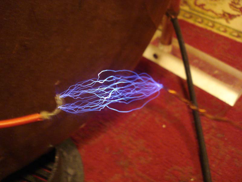
Like thus:
nav
Re: Non Linear Power Transmission With Tesla Hairpin Circuit (Alex Petty)
« Reply #50, on April 13th, 2017, 10:44 AM »
Matt it's easy to visualise on my drawing I did before your last post. The voltage or dielectricity is not able to pass the high impedance loop at the top of the hairpin and if it bounces off and comes back towards the spark gap then the standing waves will appear somewhere between the high impedance path and the lower impedance path of the spark gap. This is where voltage maxima nodes are located on closed loop transmission lines.
Place the water fuel cell on a slide tuner that moves up and down the hairpin and you'll find them.
Which means you'd let the standing waves work it's magic with the water molecules while they're bouncing back and forth and "merely" let the VIC keep the waves waving, thus drawing minimal energy from the VIC? Would that be the sentiment here?
we are lucky enough to have the original videos from the lectures that Alex was talkign about:
i created a play list:
https://www.youtube.com/playlist?list=PLsiIKXpZfLKIrGFmX3bQa5LR55dM0R0mb
enjoy
~Russ
If you go back a page Evo, you will see I got a spark gap with the hairpin circuit to 5MHz using a ZVS and Flyback. I show some of the transmitted power via scope shots and what the pulses look like if your interested.
High standing wave ratio's are usually associated with transmission line currents and are caused by either the wrong resonant length of the antenna, coax mismatch or in the case of the hairpin loop the reactances of the caps and inductor do not fall in line with the resonance of the oscillator frequency.
Tesla has produced a resonant loop antenna in the normal way we do this, by the use of capacitance/inductance tuning, an oscillator frequency and a loop of wire which the length of is not massively important. But he has also systematically detuned it at the same time by placing a lower impedance spark gap below the two capacitors. So Tesla's loop antenna has the two capacitors sat in a bottleneck of the system, the bottleneck is where the standing waves sit because its like placing a spark gap across the coax of a transmission line, instead of it being 50 Ohms, the spark gap is 5000 Ohms so the standing waves get reflected back towards the oscillator from this point. But if you have capacitors sat where the reflections are located, instead of reflecting back towards the oscillator you offer them a route of least resistance through the capacitor. like in the first picture.
But Matt wishes to place his banks of capacitors in the zone between the chokes and the high impedance node and have the spark gap on the secondary. I slightly disagree, i'd place the banks of caps like i've placed them on the second picture and have the spark gap after the chokes.