precursor to the WFCI....
some details
some details
did you know that Stan already used a micro-controller system in the 90´s when he was ready to go for industrial production?
...
Does Pgen currently calculate cell resistance via r= dV/dI?
I did know that, but the only evidence that I've seen is on the home heating unit.
...
Point being, his old technology worked, while this unit doesn't look like it operated.
...
something missing?
I did know that, but the only evidence that I've seen is on the home heating unit. This unit was designed from the ground up to use a micro-controller. The problem is that it still has the development equipment plugged on to where the IC chip goes.
...
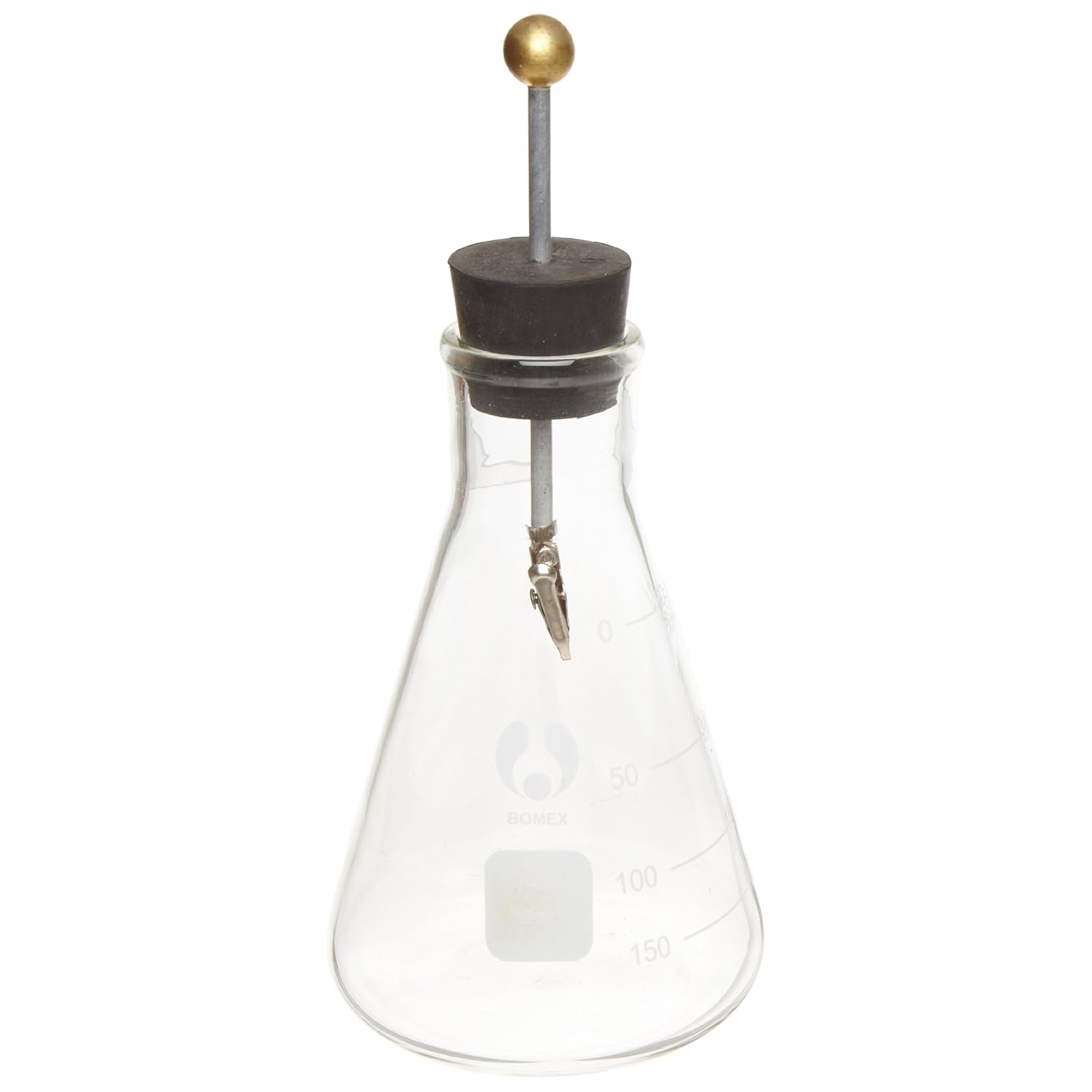
Look familiar?
I find this amazingly interesting.....
Almost seems like an antenna.
instead of brodcasting radio waves... he was broadcasting. Electrostatic pulses?
Why not. If you can charge an electroscope and have the foil plates separate, seems reasonable you could charge water and have the molecules do the same thing. Molecules form to share electrons right? So give the molecules lots of electrons and they should no longer need to share. Seems logical to me, but now we have Stan talking about electron extraction. Why does that sound backwards?
The thing to keep focused in your mind is that you can have charge without having definite polarity. A capacitor has two wires. How many wires does a metal box have? There are some Russian fellows that really grasp this idea. I'm still working on it.
sounds simple? well it is if u gra..sp the process. what must occur for a given reaction... cherrs
how do you want to create the 50KV? at what power supply resistance? DC or pulsed? if pulsed at what frequency and duty?
spell check really failed on that last post lol.
As well as the logic and reasoning analyzer.
Show me magnets splitting water.
And adding salt to the water is a really bad idea.
Free, you need to hit the bench and demonstrate what you are saying BEFORE you say it. Especially when posting in someone else's thread.
This is not easy, period. If it was, we'd all have it solved by now and fully understand how it works.
Why not. If you can charge an electroscope and have the foil plates separate, seems reasonable you could charge water and have the molecules do the same thing. Molecules form to share electrons right? So give the molecules lots of electrons and they should no longer need to share. Seems logical to me, but now we have Stan talking about electron extraction. Why does that sound backwards?
The thing to keep focused in your mind is that you can have charge without having definite polarity. A capacitor has two wires. How many wires does a metal box have? There are some Russian fellows that really grasp this idea. I'm still working on it.
still thinking about the charge without polarity statement... :thinking:
we do know that the layden jar.... has one electrode.... yet it can exibit multiple charged states..
can the layden jar be charged and yet not exibit a polarity?
if we where to have an equal amount of negative charge and possittve charge in same layden jar ..then we can
assume that it has net zero charge or no visible charge...
yet it is composed of energized particles that have been ballanced.
looking at it this way i can see that there is a potential for multiple charge states and yet exhibit no polarity....
Has anyone replicated the Electron Extraction Circuit :huh:
In the videos and speaches..
It seems that Stan is describing a progressive technological achievment..
For example one of his first "achievment" was being able to limit the current in the water fuell cell bath with the VIC.
but it wasnt till he starts talking about the "Electron Extraction Circuit" where things realy started to go into high gear.
With the "Electron Extraction Circuit" and the "resonant cavity cell" he can now achieve "on demand" gas yeild...
he mentiones this "on demand' couple times in reference to the "Resonant Cavity Cell" and "Electron Extraction Circuit"
not the VIC!
"Resonant Cavity Cell"....not very effective until we introduce the "Electron Extraction Circuit".
see acording to stan the (EEC) is what creats the condition for "higher yield" of gas....
The (EEC) in action is what allows the water to enter into a gas ionized state togheter with the resonant cavity :exclamation:
In the Resonant Cavity he talkes about "particle impact".. now upon watching his videos over and over... this is conclusion ive come to ... that the "particle impact" can only occur when the (EEC) is working properly.
See the (EEC) is the (VIC)..
In other words the (VIC) was a precursur to the (EEC) ...
not forgeting that Stan was using the Kiss methode.
I think Stan Got his master design and subdivided it into tiny little chunks for the patent office.
This makes it very hard to replicate!
In the Water Fuell Cell demo that he showed the patent office in witch most of us have replicated. He does not show the (EEC) in action!
.. Now the "Resonant Cavity" im thinking was a precursor to the (WFCI) Water Fuel Cell Injector.
And just like the original "Resonant Cavity" was not functional without the (EEC) I belive the (WFCI) is not funtional without the
(EEC).
One more insight... the (EEC) is what possibly he was using to alter gas states and testing in the (EPG).
:thinking: Has anybody out there replicated this? This is probably important peace of puzzle..
funny reading my own post and cheking for errors... I noticed the following....
This mistery: the one were voltage and Resistance rise and current falls...
all this time I havent been paying attention but it seems that this effect mimics whats called a "Negative Resister"
According to Wiki;
"In electronics, negative resistance (NR)[4] is a property of some electrical circuits and devices in which an increase in voltage across the device's terminals results in a decrease in electric current through it.
This is in contrast to an ordinary resistor in which an increase of applied voltage causes a proportional increase in current due to Ohm's law, resulting in a positive resistance.[8] While a positive resistance consumes power from current passing through it, a negative resistance produces power.[9][10] Under certain conditions it can increase the power of an electrical signal, amplifying it"
i think you started a good thread, i also think we answered all of the questions. what is left?? plenty of ways to advance..
???