Arduino VIC resonator

zchiotis

RE: Arduino VIC resonator
« Reply #50, on April 27th, 2013, 03:40 PM »Last edited on April 27th, 2013, 03:57 PM by zchiotis
Quote from firepinto on April 27th, 2013, 03:25 PM
Thanks Zchiotis,
I still need to get a 4.7V Zener diode, so I'll probably just order some new pots too.  I made a video of what I have built so far, but my internet provider (CenturyLink :@ ) decided to block youtube after my upload finished. I can't get the link to post here, but you can see it if you go to my firepinto channel.  I'll link it here when I'm out of internet detention. :dodgy:  
So far I have it scanning nothing.. but at least the LCD and LEDs are working. :cool:
Nate
Try to add a small buzzer or speaker to the output (pin 9) via 220Ω to hear it. (or hook up your oscilloscope if you have one)

If you do not connect the input to voltages over 5V there is no need for the zener. I have put it there just for the arduino safety in case the pickup coil feedback gives more voltage.
Just use a single potentiometer to 5V - pinA0 - GND. Give the highest voltage you will, and it will lock there.

Do the same for pin A1 to control gating frequency.

I would suggest to use a breadbord for your comfort, since the circuit needs more improvement
Nice video BTW.! Thanks for the feedback!!

https://www.youtube.com/watch?v=T-RgYB0-KQo

https://www.youtube.com/watch?v=T-RgYB0-KQo
Matt Watts

RE: Arduino VIC resonator
« Reply #51, on April 27th, 2013, 03:53 PM »
So guys, this is looking pretty cool.  Can one of you assemble a simple LC tank circuit and demonstrate with a video how it finds and locks on the resonant frequency?  I'd really like to see that myself.

firepinto

RE: Arduino VIC resonator
« Reply #52, on April 27th, 2013, 04:20 PM »Last edited on April 27th, 2013, 05:22 PM by firepinto
Hmm, so eventually the pick up coil may need to have the number of turns adjusted so that the VIC coil's peak operating range doesn't exceed 4.7 volts at the pick up.  Hopefully the pickup coil is supposed to peak at a different rate than the secondary / chokes.
Quote
Posted by Dog-One - Today 05:53 PM
So guys, this is looking pretty cool. Can one of you assemble a simple LC tank circuit and demonstrate with a video how it finds and locks on the resonant frequency? I'd really like to see that myself.
I'll have to refresh my memory on how to build such a circuit.  It's been too many years.:s

Nate
I have a buzzer hooked up to the output and a pot to the voltage input.  I'm getting how it works now.:D  I'll have to get to winding a VIC coil.:cool:


Is pin 13 associated with the gating?  It's pulsing the LED for it..

Nate


adys15

RE: Arduino VIC resonator
« Reply #54, on April 28th, 2013, 11:06 AM »
Quote from zchiotis on April 26th, 2013, 04:38 AM
Hello everybody,

Thanks to adys15 I have a soundcard oscilloscope!!!!!
Sorry for late repply, i am glad that I could help you.I use this scope for a long time and never dissapoint,tryed lots of sndcard scopes but there were to complex or to  low tech...here are some examples of what you could use to combine the 2 frq...Cheers

Gunther Rattay

RE: Arduino VIC resonator
« Reply #55, on April 28th, 2013, 11:44 AM »Last edited on April 28th, 2013, 12:27 PM by bussi04
Quote from firepinto on April 27th, 2013, 04:20 PM
Hmm, so eventually the pick up coil may need to have the number of turns adjusted so that the VIC coil's peak operating range doesn't exceed 4.7 volts at the pick up.  Hopefully the pickup coil is supposed to peak at a different rate than the secondary / chokes.
Quote
Posted by Dog-One - Today 05:53 PM
So guys, this is looking pretty cool. Can one of you assemble a simple LC tank circuit and demonstrate with a video how it finds and locks on the resonant frequency? I'd really like to see that myself.
I'll have to refresh my memory on how to build such a circuit.  It's been too many years.:s

Nate

I have a buzzer hooked up to the output and a pot to the voltage input.  I'm getting how it works now.:D  I'll have to get to winding a VIC coil.:cool:


Is pin 13 associated with the gating?  It's pulsing the LED for it..

Nate
first of all take a standard diode D1 to rectify AC voltage to DC halfwave (diode takes 0.7V for itself).

then just add a zener diode D2 of 5.4V in line to a resistor R3 and you clip max voltage to 5.4V. if there is more than 5.4V at the pickup R3 consumes mA flowing thru the zener D2 to drop voltage. you can add a voltage divider of 2 resistors R1 and R2 to get the range of voltage down to 6V max. (just in case that the pickup should produce voltage in the 20V range or so). C1, R5 must be calculated fitting for frequencies from 1 to 18 kHz.

C1, R5 integrate the pulse voltage so that 1 single measurement per pulse should do the job. D3 is added (and takes 0.7V for itself) so that there is no charge reflow thru R2 and calculation of R5 is easier.


adys15

RE: Arduino VIC resonator
« Reply #56, on May 21st, 2013, 07:38 AM »
Anybody tested the arduino board with vic transformer?

securesupplies

RE: Arduino VIC resonator
« Reply #57, on May 23rd, 2013, 04:03 PM »

Great Works keep going and trail it with
coil and inductors vic circuit etc

Really good to get some new tech current on here.
=====================================
I am Inviting some Parallax Controller board pro
Members to look at this thread.

As they are into more advanced solutions.

So Welcome Parallax members if you see immediate solutions please try
and than post results.

So we have More fresh input

Daniel Donatelli
www.securesupplies.biz
Sourcing & Distributing Vital Items

Gunther Rattay

RE: Arduino VIC resonator
« Reply #58, on May 24th, 2013, 01:16 AM »Last edited on May 24th, 2013, 01:21 AM by bussi04
Quote from securesupplies on May 23rd, 2013, 04:03 PM
Great Works keep going and trail it with
coil and inductors vic circuit etc

Really good to get some new tech current on here.
=====================================
I am Inviting some Parallax Controller board pro
Members to look at this thread.

As they are into more advanced solutions.

So Welcome Parallax members if you see immediate solutions please try
and than post results.

So we have More fresh input

Daniel Donatelli
www.securesupplies.biz
Sourcing & Distributing Vital Items
Newest feature added to PGen product family:

PGen phase shift control introduced at http://open-source-energy.org/?tid=469&pid=15554#pid15554

Alberto

RE: Arduino VIC resonator
« Reply #59, on July 13th, 2013, 08:15 AM »
Quote from zchiotis on April 27th, 2013, 03:40 PM
Quote from firepinto on April 27th, 2013, 03:25 PM
Thanks Zchiotis,
I still need to get a 4.7V Zener diode, so I'll probably just order some new pots too.  I made a video of what I have built so far, but my internet provider (CenturyLink :@ ) decided to block youtube after my upload finished. I can't get the link to post here, but you can see it if you go to my firepinto channel.  I'll link it here when I'm out of internet detention. :dodgy:  
So far I have it scanning nothing.. but at least the LCD and LEDs are working. :cool:
Nate
Try to add a small buzzer or speaker to the output (pin 9) via 220Ω to hear it. (or hook up your oscilloscope if you have one)

If you do not connect the input to voltages over 5V there is no need for the zener. I have put it there just for the arduino safety in case the pickup coil feedback gives more voltage.
Just use a single potentiometer to 5V - pinA0 - GND. Give the highest voltage you will, and it will lock there.

Do the same for pin A1 to control gating frequency.

I would suggest to use a breadbord for your comfort, since the circuit needs more improvement
Nice video BTW.! Thanks for the feedback!!

https://www.youtube.com/watch?v=T-RgYB0-KQo

https://www.youtube.com/watch?v=T-RgYB0-KQo
Really great stuff:exclamation:, can you please give a description
of the breadboard, mounted on the Arduino?

jtanguay

RE: Arduino VIC resonator
« Reply #60, on August 11th, 2013, 01:37 PM »
This is amazing work you guys are doing.

Key points are that Stan said his device used around a few kV and very low amperage.

One other thing I've noticed with this code is that it scans the entire frequency band to locate resonance. From what I've seen, the arduino should have no problem calculating capacitance and inductance of the circuit, do a simple calculation, and then retrieve resonant frequency (or at least VERY close) and then lock on with minor adjusting within 500ms or even 1000ms cycles.

I've also found from my research that to achieve a perfect 50% duty cycle it is damn near impossible on one chip alone. But two chips can achieve it rock solid all throughout the frequency range. Maybe that doesn't apply here since the frequency range should only be around 20khz max.

Anyone try this circuit with a step up transformer? This is from Stan's own patent:

"In the Example of a fuel cell circuit of FIG. 1, a water capacitor is included.
The step-up coil is formed on a conventional torroidal core formed of a compressed ferromagnetic powdered material that will not itself become permanently magnetized, such as the trademarked "Ferramic 06# "Permag" powder as described in Siemens Ferrites Catalog,CG-2000-002-121, (Cleveland, Ohio) No. F626-1205. The core is 1.50 inch in diameter and 0.25 inch in thickness. A primary coil of 200 turns of 24 gauge copper wire is provided and a coil of 600 turns of 36 gauge wire comprises the secondary winding."


So all one would need to do is build a similar transformer to achieve the voltage increase required. The cost to pump out one of those things would probably be in the $100+ range but the prices would go down if there were more orders I'm sure...

Alberto

RE: Arduino VIC resonator
« Reply #61, on August 30th, 2013, 03:28 PM »
It would be nice to see the voltage while scanning...
I`ve tried to change this in your program,
(0_2_9alpha), but something went wrong... :huh:

Jeff Nading

RE: Arduino VIC resonator
« Reply #62, on August 30th, 2013, 06:51 PM »
Awesome project, please keep at it.:cool::D:P


Jeff Nading

RE: Arduino VIC resonator
« Reply #65, on October 6th, 2013, 06:32 PM »
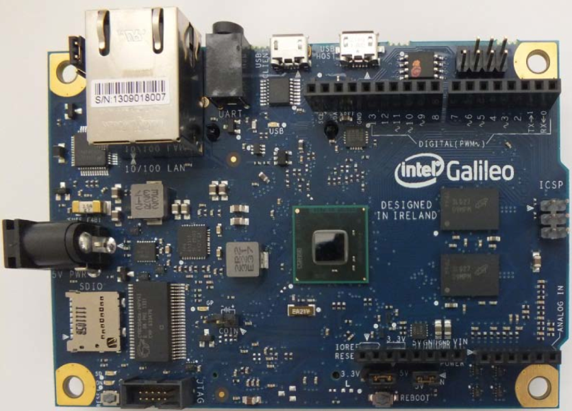
This would be an alternative to the Arduino. I did get the link to work, here is what it says about programing Nate.

Order
Number:
329681
-
001US
Programming
Galileo can be programmed with the Arduino software (
download
).
When you are ready to upload the sketch to
the board, program Galileo through the
USB Client
port by selecting "Intel Galileo" as your board in the Arduino
IDE. Connect Galileo's port
labelled
USB Client (the one closest to
the Ethernet) to your comput


Alberto

RE: Arduino VIC resonator
« Reply #69, on October 21st, 2013, 02:02 PM »
Very sad, it seems that our friend zchiotis has left the building...
Is there another C++ programmer in da house?
I should like to know how to convert a 0-1023 signal to normal voltage.
Second, is it possible to run the Arduino from 0-60kHz with output 5 & 6???

DanB

RE: Arduino VIC resonator
« Reply #70, on December 10th, 2013, 03:01 PM »
Is anyone still working on this? This could be a very useful tool.

firepinto

Re: Arduino VIC resonator
« Reply #71, on October 21st, 2014, 03:07 PM »Last edited on October 21st, 2014, 03:41 PM
So I dusted off a project I've been working at here and there.  Thought I'd post some pictures of what I have so far.  I still need to get the switching circuit breadboarded and done on a perf. board. 

I tried to keep the box modular so that it can be used with other projects just by changing the code and rerouteing some pins.  The box has a positive air pressure with the fan in the rear, which exits along the surface of the recycled heat sink.  The POT knobs are 3D printed and downloaded from thingiverse if I remember right. 


firepinto

Re: Arduino VIC resonator
« Reply #73, on October 26th, 2014, 07:13 AM »Last edited on October 26th, 2014, 07:16 AM
While testing the 0.2.10 alpha version I found some bugs that I took care of. :cool:  I also added a LED for indicating when the pick up coil and voltage divider circuit is supplying the input pin with between 4 and 5 volts.  This should help tuning, since if the input is always sensing high voltage, it won't be able to know where resonance is.  I'm thinking the voltage divider would need tweaking as the cell kicks into it's operating voltage level.

Update ver. 0.2.10 beta
-Fixed bug where pick up voltage wasnt being read while frequency was locked. This caused the auto rescan feature to no longer function
-Moved LED pins from D0 and D1 to D11 and D12.  Having a wire connected to D0 was blocking connection from the IDE through the USB serial port
-Removed Gate LED, which was no longer usable
-Added Peak Pickup Coil voltage LED, which lights between 4 and 5 volts.  (input range is 0-1023, 1023/5=204.6 per volt, 204.6*4=818.4, an input above 818 lights the LED)
-Reduced delay times for Resonance found, Waiting for Stabilization, Frequency locked. (I don't like to wait :D )
-Added comments to changes made by firepinto

Attached is a zip file with the code and the Timer1 folder which needs to be added to the Arduino libraries directory in your programs folder before you start the IDE.

Nate