Wow Well done on posting this thread, very advanced real thinking here,
:angel:
:):idea:
I have invited JN Lab to comment.
He may just do so lets see. . I really hope he try's this in his lab.
in line with his current progress.
For all members
+ Senior members "Toroid freaks"
I invite you to explain here the
VIC the +/_ you have had and if in fact You all agree with this advanced thread.
Lets Try it and see and post a result here , time to detail basic components and vics performances here, very interesting.
Attached you will find the slides, for your thought on what this thread is saying.
VERY important point was about lower resistive loads at lower voltage.
========================
Join this with gating knowledge and
hz knowledge and it seams advanced and simplified
++ the new adruino trails
lets summary it in to suggested setup and get on it , other can pick it up fast if we
start to summary these things more so many can start
Please think and post carefully .
so it == focused advance here.
http://jnaudin.free.fr/dlenz/DLE05en.htmPATENT FOR THE BI TOROID
Original document: CA2594905 (A1) ― 2009-01-18
============================================
also for reference
regen motor patent
Original document: WO2008067649 (A2) ― 2008-06-12
http://www.slideshare.net/fullscreen/ThaneCHeins/basic-physics-8524416/1=================================================
HI DO YOU HAVE A LINK FOR THAT VIDEO PLEASE.......
SOUND VERY INTERESTING
DAN
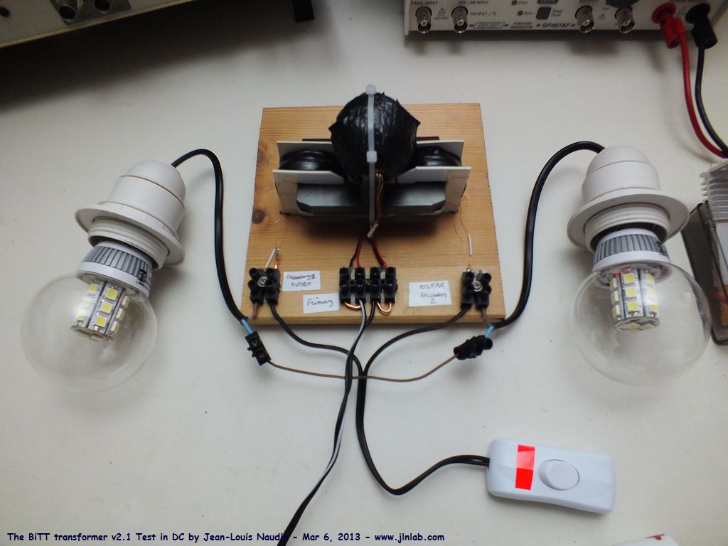
If others here on this forum haven't been following J.L. Naudin's work, it is advisable to have a look at his latest test:
http://jnaudin.free.fr/dlenz/DLE22en.htm
Apparently, the delayed Lenz effect is controllable by distance from the source of the magnetic field. As Jean demonstrates, you can set the phase angle to anything you want just with displacement. I'm still not entirely sure how to incorporate this information into a working BiTT, so I have written Jean for some advice. What this means is that ANY transformer is capable of changing the phase angle just by the relative location of the coil windings. The next trick is to figure out what phase angle you need and adjust accordingly. This would be applicable to the VIC that some are using to power a WFC.
sPECIAL INTEREST
http://www.free-energy-info.com/Chapter3.pdf
Russ & others comment
Check Pages 3-18 TO 3-20
and last Page
A total of 1.23v in conventional electrolysis. Is any higher voltage applied just a waste of energy? Perhaps it is not a step up transformer that is needed but a step down transformer from 12v to 1.2v?
Attached is the MEG pic
from Tom Beardon very interest that we are close to same tach convergence and understanding here,
Link
the final secret of free energy .tom bearden PDF
http://www.mediafire.com/view/?cpf34hl722eg9bnalso here
click folder SAVE!!!!!!
http://www.mediafire.com/?b4qpc3ag3r3jf#itj2dll96tzy2