just more. some applications..
Murray / Newman / Babcock / Tesla
~Russ
Re: Murray / Newman / Babcock / Tesla
« Reply #26, on April 18th, 2018, 01:34 PM »Last edited on April 18th, 2018, 01:46 PM
Its broke... and that's a good thing... more for us to play with :)
~Russ
~Russ
So we know that a magnetic field in a coil has momentum and inertia.
So a permanent magent would have the same right?
So we must have consistent current flowing in a coil... but in a magent its already there...
And endless flow with in the field.
Another place I think might lead to more answers on this is Faradays experiment in trying to use a DC current in 1 coil on a transformer to induce a current on the 2nd coil. When he switched the battery on and off he got current spikes in one direction and then the other in the 2nd coil.
My thinking is, when the current in the 1st coil is turned on, the electrons spin axis all line up so a magnetic field shift occurs in the core and that shift causes the current spike when its first connected as all the electrons spin axis line up all the electrons "poles" pass over the 2nd coils wires, but then when disconnected all the electrons un-align, so the current spikes the opposite way as all the electron spin axis "poles" pass over the wires while un-aligning.
Then getting back to the Faraday cage, they explain that a faraday cage will block EM fields, but not a PM field, for a PM field to be blocked you need solid sheets of conductors... so in a coil the field being created is different, or less dense? or less intense? than compared to a PM field.
idk where I'm going with this...
Funny story...
I know this person and whenever he applied an emf to a primary coil it produced an electron current which produced an expanding magnetic field. Then he would add a secondary coil and the expanding primary coil magnetic field would induce an emf in the secondary coil as well as an electron current and a secondary expanding magnetic field. The first expanding primary field induced a second expanding secondary field and the expanding secondary field then induced the primary coil in such a direction as to always increase the applied primary current or input.
I asked this person why would you keep doing something so silly?. Why would you always induce a secondary coil in such a way that the secondary induced field always reflects back inducing the primary coil increasing the primary current input and wasting energy?. Apparently he enjoyed repeating the same mistakes over and over just like everyone else without questioning what he was doing or why.
The lesson here is that what many consider to be normal and common sense can in fact be quite abnormal if not a little woo woo. Why would he keep repeating the same mistakes over and over without question?.
Should have mentioned to this silly person, why not do things in such a way where the magnetic field produced by the secondary and induced back into the primary, in no ways causes any needed increase in input power. It's not difficult to do, one just needs to think about it for a while, or go read some of my latest posts--the answer is right there in plain English.
https://en.wikipedia.org/wiki/Einstein%E2%80%93de_Haas_effect
I have been thinking like this for a while now. but this is helpful,
also, here is one of my thoughts.
What is EMF, ?
An EMF, is a force by witch the conversion between fields happens. and a CEMF is the apposing result of that conversion or change. However a CEMF appears where there are 2 of theses things happening at the same time. EX. we don't have much of a CEMF when we have an open circuit, but we do in deed have a lot of EMF. ( This EX in an "induced" EMF resulting in a "voltage" or potential difference at the ends of the wire where a current had to flow to generate this voltage). When we talk about a EMF as a result from a "moving charge" or a current, we can see the same result but in reverse. at the moment, this is what i can see an EMF is. its a result. This seems to make scene to me. at least it seems to be in the right direction. ...
id like your NON text book version of what EMF is...
~Russ
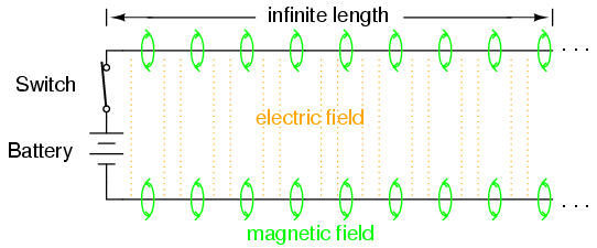
Take a look at a properly terminated (or infinite length) transmission line. On one terminal of the line you have current flowing in; the other terminal of the line you have current flowing out--equal & opposite.
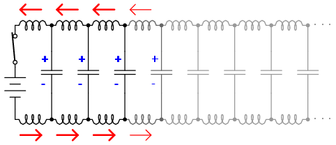
Now the kicker... In between the two conductors you have a dielectric field moving from source to terminator. So how can this be? What is really happening?
If there is any force here, it must come from the dielectric field, not the current. This implies the counter force is also from the reflected dielectric field.

The easy mistake to make is to assume EMF, voltage and dielectric field is all the same thing, but is it? When a reflected wave bounces off the load, does it not also produce current via the transmission line conductors? How do these forward and reverse currents interact?

Now the kicker... In between the two conductors you have a dielectric field moving from source to terminator. So how can this be? What is really happening?

If there is any force here, it must come from the dielectric field, not the current. This implies the counter force is also from the reflected dielectric field.

The easy mistake to make is to assume EMF, voltage and dielectric field is all the same thing, but is it? When a reflected wave bounces off the load, does it not also produce current via the transmission line conductors? How do these forward and reverse currents interact?
talisman
Re: Murray / Newman / Babcock / Tesla
« Reply #34, on May 1st, 2018, 02:17 AM »Last edited on May 1st, 2018, 02:25 AM
EMF: electromotive force is the physical quantum motion by force applied to a mass from electromagnetism.
Voltage: is the potential force difference between a positive and negative pole.
The dielectric field: is the electromagnetic field of attraction or repulsion between a polar force gradient.
Voltage: is the potential force difference between a positive and negative pole.
The dielectric field: is the electromagnetic field of attraction or repulsion between a polar force gradient.
Thanks for the replies.
some deep thoughts there.
I need to keep thinking as well...
~Russ
some deep thoughts there.
I need to keep thinking as well...
~Russ
talisman
Re: Murray / Newman / Babcock / Tesla
« Reply #36, on May 1st, 2018, 11:11 PM »Last edited on May 1st, 2018, 11:19 PM
I was just looking at some video of the upcoming energy science conference (Aaron Murikami).
These inventors have a lot of experience. Some of them might be working on different concepts or ideas.
By having the same definitions in a context (here a physical mechanical generator) there is clarity.
The basic definitions of energy, work and power being consistent are a baseline.
The multiple other definitions in energy translators or generators are sometimes a little different in view.
The characteristics of voltage with a high power and frequency from a transmission view
can be of a different quality than that from a motor engineering view or a physic math view that shares numerals.
On the topic of voltage we think of potential for transformation.
It is an energy state for an electron.
In circuit theory it is all electrons, positive and negative.
In fact all electrons are negatively charged.
There is a positive and charge no such thing as a positive electron.
There are positive and negative volts and no such thing as a positive electron.
The potential is between a quantity of protons and electrons.
The energy transfer mechanism is the neutron.
The electron has a mass that is approximately 1/1836 that of the proton.
https://pps2.com/smf/index.php?topic=33.0
must fully understand the separate quadrants, there are four categories (+W/+vars, +W/-vars, -W/+vars, -W/-vars)
~Russ
must fully understand the separate quadrants, there are four categories (+W/+vars, +W/-vars, -W/+vars, -W/-vars)
~Russ
~Russ
Re: Murray / Newman / Babcock / Tesla
« Reply #39, on May 4th, 2018, 09:15 AM »Last edited on May 4th, 2018, 11:49 AM
"The power generator can be considered as a voltage source with an electromotive force and a source impedance which in the case of the utility supply very small. The power factors are defined for loads not for power sources"
source.
https://www.researchgate.net/post/Reactive_loads_such_as_L_and_C_dissipate_zero_power_yet_the_fact_that_they_drop_voltage_draw_current_gives_impression_that_they_do_dissipate_power
a load with a PF of 0 and a
so, lets say you isolate the Source from the Load. so that you have Absolute 0 power in the circuit. seen by the source.. but you have real current flowing through the load. and the Net power is more than 0.
this gets confusing because there are 2 things here to look at. the source from the power plant and the local source to the local load.
we get docked by the power plants to have a bad PF ( industrial places do) . so we kinda want the good PF on one side of the circuit. we want the power to go back to the source and show up as a Absolute 0 power. but in the load we want to see this reactive power.
Take a transformer, consider the primary a load for the power company, and consider the secondary a source for your local load.
now, If the local load and the local source are working together to achieve a power factor = 0 then the source sees no load.
and that reflects back to the primary as a "no load" Yet the power company still sees a PF = 1 but with virtually no load.
so now both sides are happy.
now the real discussion. if you have purely reactive circuit. your doing nothing but moving ENERGY around... no POWER is available... only ENERGY. ( in the forum of a magnetic field or a dielectric field )
yes if i place a resistor in the line where the ENERGY is going back and forth... will it not get hot? Ihis is the result of " WATTLESS POWER"
something to think about...
This goes back to the question of dose the load consume the ENERGY?
...
~Russ
~Russ
Re: Murray / Newman / Babcock / Tesla
« Reply #40, on May 4th, 2018, 11:38 AM »Last edited on May 4th, 2018, 11:54 AM
to my point,
look at the Load vs the source.
You can see that the load ( lights, or resistor) are getting in phase power and voltage.
but the transformer "sees" reactive power. in fact the current is flipped every 1/4 cycle where the voltage is every 1/2 cycle...
Gets a bit confusing but for 1/2 the cycle power is going back this is done every 1/4 cycle its a give take...
"your not creating energy, but your making use of the difference between the Net work done and the absolute work done. "
Now the hard one to understand. if you can send back Negative watts... then the only way to really do this is to have an ENERGY amplifier... the result of ENERGY moving is work done in the resistor or load.
Resonance implies that you are adding energy in to the system a little at at time.
ENERGY amplifier implies that you are amplifying the energy that is with in...
~Russ
If you talk about reacative power. You normialy talk about phase shifts, however if the motive force stays the same and the current flip every 1/4 cycle then the VA and the VAR are in phase still.... but the source sees the system as no load.
Question then: If one where to drive a transformer with a lossless clamp circuit and have the secondary utilize these principals (as in the SERPS application), could you not power a resistive load for essentially no DC input power?
some wave forum analysis.
Question then: If one where to drive a transformer with a lossless clamp circuit and have the secondary utilize these principals (as in the SERPS application), could you not power a resistive load for essentially no DC input power?
I'm not familiar enough with the lossless clamp circuit...
ill have to think about it more.
~Russ
Matt Watts
Re: Murray / Newman / Babcock / Tesla
« Reply #45, on May 4th, 2018, 04:56 PM »Last edited on May 4th, 2018, 08:09 PM
I dont know...
I'm not familiar enough with the lossless clamp circuit...
BTW, the lossless clamp circuit above was designed and posted by Verpies at overunity.com, built and tested by Itsu with excellent results. Notice the only real difference between it and a typical push-pull driver is the addition of bifilar windings on the primary which is used as the recovery mechanism. I designed a push-pull driver for the Ruslan device using snubbers which dissipate reflected energy as heat. The lossless clamp is many times more efficient.
"An EMF is the Force that pushes current.
The current passing thought an impedance..., The pressure of the charge that can not flow through the impedance somotanisly is what develops the phenom we call voltage... "
From JIM...
~Russ
The current passing thought an impedance..., The pressure of the charge that can not flow through the impedance somotanisly is what develops the phenom we call voltage... "
From JIM...
~Russ
Matt Watts
Re: Murray / Newman / Babcock / Tesla
« Reply #47, on May 5th, 2018, 12:41 AM »Last edited on May 5th, 2018, 01:01 AM
So the corollary is that IF charge CAN flow through an impedance spontaneously, then the voltage should be zero, correct?
Like in the case of a shunt or direct short.
Like in the case of a shunt or direct short.
~Russ
Re: Murray / Newman / Babcock / Tesla
« Reply #48, on May 5th, 2018, 10:20 AM »Last edited on May 5th, 2018, 10:25 AM
So the corollary is that IF charge CAN flow through an impedance spontaneously, then the voltage should be zero, correct?
Like in the case of a shunt or direct short.
We can say that there is an impedance there. (Open circuit) Becuse we have voltage... and there is an EMF as well or we would have no voltage.
Then we connect a light across the outputs And mesure again and get 50v .
We ask our selfs where has the other 50v gone? Well...
its gone in to the genarator coil making the voltage. So there is impedance there in thst coil still.
If there was none then we would see all of this voltage dropped across the light.
The qustion is how do we fix this?
(Hint. Transforming genarator dose this by adding a second coil, each coil fixes this problem for the other coil... but how?)
After some thinking. I will try to answer this in Jim's words
~Russ
"THE MAGNIFYING TRANSMITTER.
I have been asked by the Electrical Experimenter to be quite explicit on this subject so that my young friends among the readers of the magazine will clearly understand the construction and operation of my “Magnifying Transmitter” and the purposes for which it is intended. Well, then, in the first place, it is a resonant transformer with a secondary in which the parts, charged to a high potential, are of considerable area and arranged in space along ideal enveloping surfaces of very large radii of curvature, and at proper distances from one another thereby insuring a small electric surface density everywhere so that no leak can occur even if the conductor is bare. It is suitable for any frequency, from a few to many thousands of cycles per second, and can be used in the production of currents of tremendous volume and moderate pressure, or of smaller amperage and immense electro-motive force. The maximum electric tension is merely dependent on the curvature of the surfaces on which the charged elements are situated and the area of the latter."
https://teslauniverse.com/nikola-tesla/articles/my-inventions-v-magnifying-transmitter