AC resonance and DC cancellation, understanding where our voltage goes.

nav

AC resonance and DC cancellation, understanding where our voltage goes.
« on June 11th, 2017, 06:43 AM »Last edited on June 11th, 2017, 07:20 AM
Doing this thread to try to comprehend what is happening to the DC voltage we create on the fuel cell at AC resonance. Recently i've learned quite a bit about Stan's circuitry by seperating the primary and secondary from the chokes. By doing this it allows us to understand what happens in the circuitry much better and where the voltage is sitting together with a better understanding of where the voltage goes.
So we know that there is an LC circuit taking place between the cell and the chokes and here is a picture of it from my recent experiments.

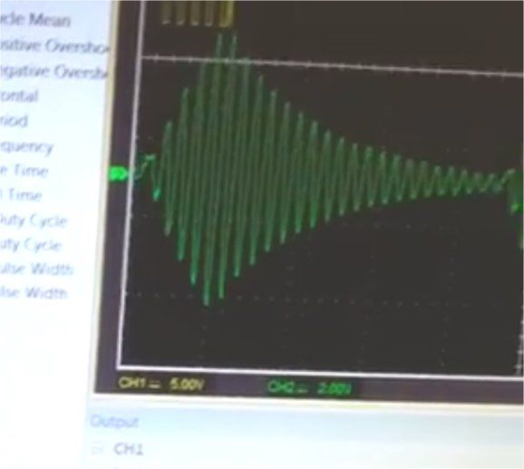
So what do we know about this LC network between the chokes and the cell? Well, even though a diode exists we know that the resonance is actually AC resonance and it rides the series diode and we know that the DC responds to the AC signal because without it then the DC simply fails to materialise and we need the DC for the cell to perform work.
First thing to understand about LC networks: If you create an LC network between one inductor and one capacitor the reactance is equal and cancelling so that no AC or DC bias exists and that is a fact of life. It happens because each 180 degree phase of an AC signal is equal by definition because the inductor behaves exactly the same in one direction as it does in the other. Ed Mitchell has been commenting recently on my Youtube video's and has mentioned that the reactance of the cell is different from the chokes and it is this fact that creates the DC bias on the cell. That is impossible and i'll tell you why:
Any LC resonance at AC decides its own self resonant frequency, we as experimenters cannot decide such a frequency in any way shape or form, it is the reactance of the capacitor and the reactance of the inductor that chose where the frequency sits and that frequency is always equal reactance. If you had a notion that you wanted the cell to be more reactive than the chokes then that is impossible because the very nature of LC resonance equals ALL reactances to a level playing field. There can be no bias anywhere in this scenario.
So lets move on and look at this following drawing:

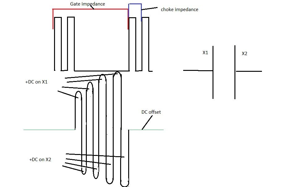
In the drawing you will see a square wave pulse at the top with two frequencies, the first frequency is the gate frequency which is driving a resistor or a spark gap, the second frequency is an higher frequency which is driving our chokes and cell. The high frequency signal is being choked from the low frequency signal at an high impedance. The reason it is high impedance is because the resistance across the water gap in the fuel cell is very high at that particular frequency.
Now, the AC resonance drawed below the square wave which is responding to the square wave pings taking place is LC resonance between the chokes and the water fuel cell and it ignores any diode in the series circuit and as with all capacitors a DC value is placed on X1 cap plate BUT the equal positive charge is also placed on the X2 plate when the AC signal passes through the other 180 degrees of it's signal. What this means is besides the equal AC reactance taking place between the cell and the chokes there is also cancellation of DC voltage taking place on the cell.
Now look at this drawing:

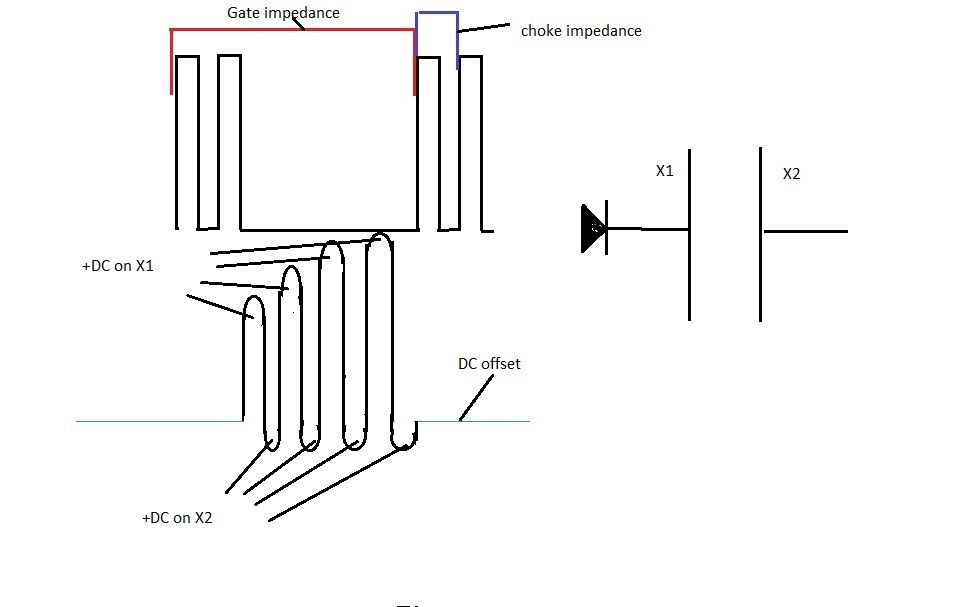
You will notice that through the first 180 degrees of AC resonance between the chokes and the cell a +DC value has built up on X1 capacitor plate but through the next 180 degrees of the AC phase, the +DC value is missing from X2 cap plate. HOW DOES THIS HAPPEN?
We created a DC bias from an AC signal did we not? The reason it happens is in fact very simple, L1 which created the initial +DC voltage on X1 is of higher reactance than L2 and you have to look on a scope at low voltage to understand this. When the initial AC wave form hits resonance and an LC network forms between the chokes and the cell it is NOT a mean everage of L1+L2 and the cell, The first 180 degrees of the AC signal uses the higher reactance of L1 to place +DC on X1 cap plate and L2 is trailing. On the opposite 180 degrees of the AC signal, L2 has less reactance with the cell and L1 is trailing. This difference in reactance at AC is what causes a DC bias on X1 capacitor plate. The diode in the series circuit stops the DC bias on X1 from escaping back into the system.
The system is step charging the DC bias because of a difference in reactance when L1 is at the leading edge and when L2 is at the leading edge of each respective 180 degree phase. Why does this happen and why are both 180 degree signals NOT a mean average of both L1 and L2?
It is because the cell's reactance is being tricked, the cell thinks there is just one inductor and it is creating an LC network with one inductor, it resonates with L1 in 180 degree's of the phase then resonates with L2 in the other 180 degrees thinking it's the same inductor at the same reactance but L2 has less reactance and so the bias is left behind.

Matt Watts

Re: AC resonance and DC cancellation, understanding where our voltage goes.
« Reply #1, on June 11th, 2017, 08:26 AM »Last edited on June 11th, 2017, 08:44 AM
Quote from nav on June 11th, 2017, 06:43 AM
This difference in reactance at AC is what causes a DC bias on X1 capacitor plate. The diode in the series circuit stops the DC bias on X1 from escaping back into the system.
Stan termed this diode as a "blocking diode" for a reason which you make perfectly clear.
Quote from nav on June 11th, 2017, 06:43 AM
The system is step charging the DC bias because of a difference in reactance when L1 is at the leading edge and when L2 is at the leading edge of each respective 180 degree phase. Why does this happen and why are both 180 degree signals NOT a mean average of both L1 and L2?
It is because the cell's reactance is being tricked, the cell thinks there is just one inductor and it is creating an LC network with one inductor, it resonates with L1 in 180 degree's of the phase then resonates with L2 in the other 180 degrees thinking it's the same inductor at the same reactance but L2 has less reactance and so the bias is left behind.
Tom Bearden referred to this process as "regauging".  You bring the voltage up to some level, then you reset the zero reference and apply another cycle.  Each cycle allows the cell voltage to climb to higher and higher levels referenced to the initial zero point.  As long as the cell is referenced to the initial zero point and the chokes to the ever increasing reference point, the end result is a cell with considerable charge separation, which is exactly what we want.  The trick you mention is to never let the chokes see the initial reference point, because if they do, they reset and all our voltage gain at the cell is gone.

If you try to think of this whole deal as stacking batteries in series, it begins to make a little more sense.  What you have to do though is think of the stacks of batteries as virtual batteries--they are not really there, but the system thinks they are.  The way to do that is to make these virtual batteries appear with a certain impedance.  So you have 1000 volts on the cell and the cell sees an impedance that also looks like 1000 volts--no charge flow.  So now you add another battery that makes the impedance look like 2000 volts.  Now the cell must take on charge and will continue to do so until it reaches 2000 volts.  Add another real battery to the already two virtual batteries.  Rinse and repeat.  While doing all this, the chokes only see the one real battery, but the cell sees the one real battery in series with all the virtual batteries.  And as long as those have a higher voltage than the cell, the cell continues to charge.

As far as Mr. Mitchell is concerned, he's done a lot of hard work, but I'm afraid he has hit a wall or painted himself in a corner.  It's still a good place to experiment and get a better understanding of the real workings behind this technology and you're doing a great job Nav.  I'll be really surprised if you not only get this thing working, but find a more straight forward, easier way to make it work.

Matt Watts

Re: AC resonance and DC cancellation, understanding where our voltage goes.
« Reply #2, on June 11th, 2017, 08:56 AM »
Something else I have been toying with Nav, that you may take into consideration:  Rise and fall times.

I've noticed with various LC circuits if you hit them hard with rapid rise times, they push back.  In some instances they almost appear to push back harder than the initial push of the signal generator.  What I'm discovering is the child on a swing scenario is a real down to earth concept, even with electrical devices.  You don't smack the child in the back with a sledge hammer.  You gently push with a speed only slightly higher than the child in the swing is moving.  Once you make contact, you push a little harder.  At the point of disengagement, you gently back off your push.  This is the way we should be pulsing our coils and driving our motors.  When you do this, you'll notice straight away the ease in which you can build resonance.  Impedance to this type of pushing force goes nearly to zero.  When the impedance drops away, so does reactance, or should I say, negative reactance.  The system almost appears to function on its own and in my mind, that's a good thing.


nav

Re: AC resonance and DC cancellation, understanding where our voltage goes.
« Reply #3, on June 11th, 2017, 09:28 AM »
Quote from Matt Watts on June 11th, 2017, 08:26 AM
Stan termed this diode as a "blocking diode" for a reason which you make perfectly clear.

Tom Bearden referred to this process as "regauging".  You bring the voltage up to some level, then you reset the zero reference and apply another cycle.  Each cycle allows the cell voltage to climb to higher and higher levels referenced to the initial zero point.  As long as the cell if referenced to the initial zero point and the chokes to the ever increasing reference point, the end result is a cell with considerable charge separation, which is exactly what we want.  The trick you mention is to never let the chokes see the initial reference point, because if they do, they reset and all our voltage gain at the cell is gone.

If you try to think of this whole deal as stacking batteries in series, it begins to make a little more sense.  What you have to do though is think of the stacks of batteries as virtual batteries--they are not really there, but the system thinks they are.  The way to do that is to make these virtual batteries appear with a certain impedance.  So you have 1000 volts on the cell and the cell sees an impedance that also looks like 1000 volts--no charge flow.  So now you add another battery that makes the impedance look like 2000 volts.  Now the cell must take on charge and will continue to do so until it reaches 2000 volts.  Add another battery.  Rinse and repeat.
Correct!
You must try to imagine the capacitor already has one million vdc sat on it before we do anything. What ever we do then it becomes one million volts plus the step charge. So lets just say after 5 milliseconds we get 1000v on the cell, then that is 1000vdc plus a million volts becomes the new circuit ground which is isolated from everything else. The cell DC voltage must always be a new neutral reference point after every cycle and the chokes treat it as such because the chokes cannot see the DC bias.
So we isolate the chokes from the DC bias with a diode by only allowing them to resonate at AC resonance during pulse off but during pulse on we must also stop the DC bias from referencing system ground.
We can see the difference in reactance on the below tables which Dom provided. Notice the inductance of L1 and L2 at 1khz and also the resistance at 1khz. This is where the DC bias gets formed but the trick is how to keep it on the cap.


nav

Re: AC resonance and DC cancellation, understanding where our voltage goes.
« Reply #4, on June 11th, 2017, 09:38 AM »
You will also notice that the secondary is a mean average of the two and there is a reason behind that. The secondary MUST be a mean average of both L1 and L2 reactance with the cell otherwise it will cause bias either toward L1 or bias toward L2 and screw the DC bias between L1 and L2 and the cell. The secondary coil is a neutral swing in a push pull system that neither effects L1 nor L2. The diode doubles the frequency between the secondary and L1 which allows the frequency of L1 to fall in phase with the self resonance at AC between the chokes and the cell.

nav

Re: AC resonance and DC cancellation, understanding where our voltage goes.
« Reply #5, on June 11th, 2017, 10:20 AM »
Quote from Matt Watts on June 11th, 2017, 08:56 AM
Something else I have been toying with Nav, that you may take into consideration:  Rise and fall times.

I've noticed with various LC circuits if you hit them hard with rapid rise times, they push back.  In some instances they almost appear to push back harder than the initial push of the signal generator.  What I'm discovering is the child on a swing scenario is a real down to earth concept, even with electrical devices.  You don't smack the child in the back with a sledge hammer.  You gently push with a speed only slightly higher than the child in the swing is moving.  Once you make contact, you push a little harder.  At the point of disengagement, you gently back off your push.  This is the way we should be pulsing our coils and driving our motors.  When you do this, you'll notice straight away the ease in which you can build resonance.  Impedance to this type of pushing force goes nearly to zero.  When the impedance drops away, so does reactance, or should I say, negative reactance.  The system almost appears to function on its own and in my mind, that's a good thing.
The biggest problem in all tank circuits is the very nature of the oscillations have a cancelling effect especially with a single inductor and capacitor. The self inductance and capacitance of the tank are equal so that the resistance eventually eats them away to nothing as viewed on the scope with any tank circuit. What you need is a lob sided push pull effect where when you push the girl on the swing, everything is in phase so that all the pushes and pulls provide as little resistance as is possible but you sneak a little bit of the push away and isolate it from everything else and keep it there.
AC and DC are a God send, mainly because you can create a DC voltage aside from an AC oscillation under no load which usually gets cancelled in the reactance. BUT...if those oscillations are not equal during both halves of a 360 degree phase then the reactance won't be equal, the cancelling effect and reactance change on the DC while still under no load. Because the DC bias is created in self resonance of an inductor and capacitor, it takes little energy to ping that network into life.
Imagine a tuning fork in one hand and you place one in the other hand and you tap one fork bringing the other to life, well imagine a million tuning forks in the same room all doing the same, at what point do you say there is more energy in the million tuning forks than the original one? The tuning fork vibrates the air in the room and anything that is tuned to the same frequency will vibrate but there will come a point when the more tuning forks you have, it will dampen the effect in the room by absorbing energy until there is no air left vibrating. Stan is doing the same in a way, he's vibrating instruments until the damping effect of resistance stops it but he's detuned one fork leg so that it's slightly out of tune and the detuning creates a stored energy that is not recognised by the resonance.

nav

Re: AC resonance and DC cancellation, understanding where our voltage goes.
« Reply #6, on June 11th, 2017, 10:53 AM »
So Matt, we set out not to just copy Stan's work but to understand how it works step by step and fully understand the technology so that we can build our own systems with basic principles of knowledge.
We know things this week that we knew last week but we've further elaborated on that knowledge base. Stan said in his video's that he covered every angle possible in his patents which involved using voltage to split water. He stated in the New Zealand video that we can use audio transformers in the build but they have to be precisely built around when matching the chokes so that you can't just build any old choke to any old audio transformer. By using audio transformers we know that the chokes can be seperate from the primary and secondary but we must know the difference between a five coil VIC and seperate primary/secondary. The difference is you must privide DC bias isolation and therefore choke isolation from the primary in a different way than the five coil VIC does but it still can be done if you think about it.
Where does this leave us now? Where do we go from here? What do we know this week that we didn't know last week and what Ronnie did?
I think there are several points which we can all learn from during building.
Firstly, the name of the game is LC resonance between the chokes and the cell which ever circuit you build. Get the resonance going and learn how to do it.
Secondly, experiment in creating L1 with an higher reactance than L2 and a secondary that sits between as a mean average of the two, do everything at low voltage and watch the scope carefully because you are looking out for a DC bias which builds at the AC LC resonance and cannot escape. If the DC starts to build but is getting cancelled then look at isolating your choke circuit in a better way. Always remember that isolation means any voltages in the choke circuit must never come into contact with the primary impedance otherwise the DC bias will be put to death on every cycle.

nav

Re: AC resonance and DC cancellation, understanding where our voltage goes.
« Reply #7, on June 11th, 2017, 12:04 PM »
I'll give people some great advice though which is important: When you are watching the LC resonance on the scope in comparison with the pulse frequency, watch what happens when you go up and down in pulse frequency and watch what happens to the phase relationship between the pulse and the LC resonance then watch the current and peak to peak voltages. You can pull the chokes in or out of phase with the secondary, you can pull them 180 degrees out of phase, 90, 30, 270 or any configuration you please just by frequency adjustment. The LC resonance between the chokes and the cell will always remain the same frequency wise but the main pulse can be changed to alter phase. This is handy to know when you go for isolation of the DC bias from the primary because Stan tells us so and is part of the 5 coil VIC technology.
When you go for physical isolation with a T1 and a T2 system, the phase difference is important otherwise isolation gets screwed up a little but you'll get the idea when you see the scope because it won't happen unless you get it right. Ed Mitchell says this technology is incredibly complicated and hard to achieve, I disagree and I put it to the forum and Ed that this technology is simple low pass filters doing nothing other than filtering unwanted signals from the line and anyone can do it. The trick is filtering those signals into a cap and keeping them there instead of letting reactance and system ground destroy them. One day this technology will be more common the a tomato slicer technology but convincing others that this will be the case is not easy. Keep at everyone, we are nearly there.

chuff1

Re: AC resonance and DC cancellation, understanding where our voltage goes.
« Reply #8, on June 12th, 2017, 01:03 PM »Last edited on June 13th, 2017, 04:09 PM
I am not sure if this idea has been thought about but here are some quick thoughts
that come to mind while reading these post.  First is the LC resonance of the coils
and the capacitor (aka the cell) it would seem impossible to drive a LC circuit to resonance
with a capacity that always changes without having a feedback circuit that would
adjust to the waters dielectric changes and also resistance changes.  So the thought
was to use a Hartley oscillator in loo of a driving circuit.  This method seems most logical
for it to find its own resonant freq by using the cell as the variable capacitor.  As to the reason
to drive it at its resonant frequency, if the whole objective is to create charge separation
using the highest voltage on the plates then would it not be easier to not use the cell as
the capacitor and drive it on the secondary side with a primary side LC circuit?