Finally we are absolutely on the brink of making history.
During more testing some things have finally being cleared up to answer many questions for many people.
It will answer Matt's resistance question and it will allow people to get their VIC working if you follow some simple steps, I kid you not.
Now where the hell do I start and how can I explain this easily? We begin with a question.
Why did I produce a 1000v on my cell with Matt's spark gap and why wouldn't it operate without a gate?
Any choke in any circuit in the world can only work when there are two line impedances. The main line impedance and an unwanted impedance you wish to choke. Stans circuit without a gate after the diode only produces one impedance figure which is an high frequency, high impedance signal. So ask yourself 'how can you choke this signal from the line without another signal being present'? The answer is you can't, you can choke low impedance out of an high impedance circuit or choke high impedance out of a low impedance circuit so for Stan to choke high impedance there has to be another low impedance signal present but where is it?
It's the gate
When we introduced the spark gap we created a low impedance circuit in parallel with the water fuel cell but it was not being driven by high frequency, it was driven by the low frequency of the gate and thats why when I turned off the gate the system shut down.
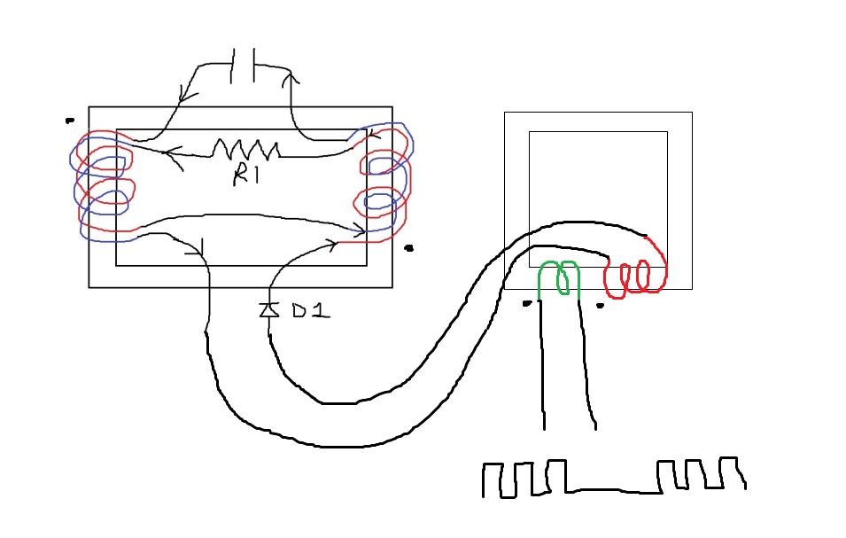
Did more testing with my new choke and a simple stand alone transformer yesterday night, basically I did the following circuit.
Now first things first lets get one thing absolutely clear
The most important thing is to feed current through the resistor at R1 at a low impedance and that means firstly that the resistor has to be the value of both choke's plus the secondary of the stand alone transformer and in my case it was 50ohms+50ohms+300ohms which was 400ohms. I had to use a variable to do it because I didn't have one. Start with voltage of 3v coming out of the tip3055 btw.
Then what you do is set the gate to 50% duty cycle width and this is your low impedance pulse not the main frequency and i'll explain why later. Play around with the gate frequency until you get the most current passing across the resistor R1 but not creating inductance in the choke core. Keep your main frequency nice and low while you do this testing. A nice tip: Use the air gaps in your choke core to change where the choke will and will not become inductive
The current of the gate is ignoring the inductors and only responding to the resistor R1 at this lower impedance value.
Now folks hold onto your hats
Let the circuit run with the gate where you set it with most current in the resistor R1 but start to increase the main pulse slowly, there is a point in frequency where the choke is able to be the most inductive at an higher frequency and it starts to absorb the high impedance/high frequency signal as inductance. Now you have two signals in the circuit, the leading edge of each gate is low impedance and the leading edge of each main pulse is high impedance. When you go up in voltage, the frequency of the main pulse and gate has to change so take it volt by volt, there is no PLL in my system.
The resonance of the chokes are nothing to do with an LC circuit, the resonance is where the chokes inductance and magnetising force is highest and choke the high frequency, high impedance pulse, the WFC is a dump capacitor from a low pass resonant filter.
We have fooled ourselves into thinking Stan's chokes were the main part of the circuit when in fact the low impedance Resistor in series with my secondary is the main part of the circuit and all we are doing is filtering an higher frequency from the circuit.
We filter it with an inductor and core that is most inductive at the unwanted frequency.
People, you need to build or start building and you need to hook up your scopes and look at what i'm saying.
Matt, thankyou so much for what you did with the spark gap because without the idea this would have never happened.
Let the fun begin. I'll make a vid soon but got lots of parts on order at moment, i'm going to drive a central heating system with it firstly.
During more testing some things have finally being cleared up to answer many questions for many people.
It will answer Matt's resistance question and it will allow people to get their VIC working if you follow some simple steps, I kid you not.
Now where the hell do I start and how can I explain this easily? We begin with a question.
Why did I produce a 1000v on my cell with Matt's spark gap and why wouldn't it operate without a gate?
Any choke in any circuit in the world can only work when there are two line impedances. The main line impedance and an unwanted impedance you wish to choke. Stans circuit without a gate after the diode only produces one impedance figure which is an high frequency, high impedance signal. So ask yourself 'how can you choke this signal from the line without another signal being present'? The answer is you can't, you can choke low impedance out of an high impedance circuit or choke high impedance out of a low impedance circuit so for Stan to choke high impedance there has to be another low impedance signal present but where is it?
It's the gate
When we introduced the spark gap we created a low impedance circuit in parallel with the water fuel cell but it was not being driven by high frequency, it was driven by the low frequency of the gate and thats why when I turned off the gate the system shut down.
Did more testing with my new choke and a simple stand alone transformer yesterday night, basically I did the following circuit.

Now first things first lets get one thing absolutely clear
The most important thing is to feed current through the resistor at R1 at a low impedance and that means firstly that the resistor has to be the value of both choke's plus the secondary of the stand alone transformer and in my case it was 50ohms+50ohms+300ohms which was 400ohms. I had to use a variable to do it because I didn't have one. Start with voltage of 3v coming out of the tip3055 btw.
Then what you do is set the gate to 50% duty cycle width and this is your low impedance pulse not the main frequency and i'll explain why later. Play around with the gate frequency until you get the most current passing across the resistor R1 but not creating inductance in the choke core. Keep your main frequency nice and low while you do this testing. A nice tip: Use the air gaps in your choke core to change where the choke will and will not become inductive
The current of the gate is ignoring the inductors and only responding to the resistor R1 at this lower impedance value.
Now folks hold onto your hats
Let the circuit run with the gate where you set it with most current in the resistor R1 but start to increase the main pulse slowly, there is a point in frequency where the choke is able to be the most inductive at an higher frequency and it starts to absorb the high impedance/high frequency signal as inductance. Now you have two signals in the circuit, the leading edge of each gate is low impedance and the leading edge of each main pulse is high impedance. When you go up in voltage, the frequency of the main pulse and gate has to change so take it volt by volt, there is no PLL in my system.
The resonance of the chokes are nothing to do with an LC circuit, the resonance is where the chokes inductance and magnetising force is highest and choke the high frequency, high impedance pulse, the WFC is a dump capacitor from a low pass resonant filter.
We have fooled ourselves into thinking Stan's chokes were the main part of the circuit when in fact the low impedance Resistor in series with my secondary is the main part of the circuit and all we are doing is filtering an higher frequency from the circuit.
We filter it with an inductor and core that is most inductive at the unwanted frequency.
People, you need to build or start building and you need to hook up your scopes and look at what i'm saying.
Matt, thankyou so much for what you did with the spark gap because without the idea this would have never happened.
Let the fun begin. I'll make a vid soon but got lots of parts on order at moment, i'm going to drive a central heating system with it firstly.