please help w/simple question re: fan speed control circuit

Over Goat

please help w/simple question re: fan speed control circuit
« on December 30th, 2014, 01:27 PM »Last edited on December 30th, 2014, 08:22 PM
I am trying to make a heater which will work exactly as described in online instructions, and one part
calls for a fan speed control circuit added to the heater as described here:
Quote


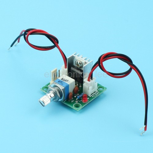
needed For fan speed controller:
 LM317
resistance - 100ohms, 1kohm pot
 capacitors- 0.1uf, 10v 100uf

Air flow control is done by regulating the speed of dc motor -> which is done by regulating dc voltage.  to regulate dc voltage i used LM317 ic which easily regulate the voltage over 3-10volts as mentioned above circuit.  there input can be12v output from computer supply.
would I have to make the above described circuit  board myself, exactly as specified above, for it to work, or could I use a ready made board like this one?

this one has a fan speed knob built into it, so presumably it might work?

http://www.ebay.com/itm/LM317-Linear-Full-stage-Voltage-Regulator-Board-Fan-Speed-control-w-Switch-/271607513142

I am new to this , so I find it hard to understand what he means and its not clearly written either.
does the plan call for the fan to be regulated to use between 3 and 10 volts ?
He has the fan connected to a  5 volt plug of a computer power supply and his
ESL writing is hard to understand. Can it use over five volts at all if connected to that
5 volt plug?


 I am a complete, complete newbie to this, and I don't have
meters and things to work with, so I am trying to find a way to make this by ordering pre-made
parts like the fan speed control for it:

the plan also calls for a temperature control circuit, and again its  something I hope to find ready made which I can buy.  if you are interested have a look


~Russ

Re: please help w/simple question re: fan speed control circuit
« Reply #1, on December 30th, 2014, 03:28 PM »Last edited on December 30th, 2014, 03:32 PM
hi!

there are a bunch of pree maid circuits such as the one you posted here.

those will work fine and there is know need to start from scratch if you can get a board already maid. it may even be cheaper.

it appears that he is running 12V to the peltier and 5V to the fan.

im not sure why he would not run 12V to the fan, but you will only get out what you put in, so if 5V in to the regulator than only 0-5V out

on the other control circuit its just a timer that turns on and off to regulate the input. this will regulate the output temp.

hope this helps!


~Russ

Over Goat

Re: please help w/simple question re: fan speed control circuit
« Reply #2, on December 30th, 2014, 03:35 PM »
Quote from ~Russ on December 30th, 2014, 03:28 PM
hi!

there are a bunch of pree maid circuits such as the one you posted here.

those will work fine and there is know need to start from scratch if you can get a board already maid. it may even be cheaper.

it appears that he is running 12V to the peltier and 5V to the fan.

im not sure why he would not run 12V to the fan, but you will only get out what you put in, so if 5V in to the regulator than only 0-5V out

on the other control circuit its just a timer that turns on and off to regulate the input. this will regulate the output temp.

hope this helps!


~Russ
thanks, Russ, so why does he have a regulator at all? just to adjust the heat of the fan?
and can I get a cheap timer circuit board which will work for a couple of bucks?

~Russ

Re: please help w/simple question re: fan speed control circuit
« Reply #3, on December 30th, 2014, 03:47 PM »
you can get all the parts at radio shack to build the timer. but im sure there is a board out there. it just may be more versatility than you need. thus more pricy. 

also electronic switch. such as this is better than a relay for this setup: http://www.pcbheaven.com/circuitpages/PWM_Fan_controller_using_a_555/

i guess the regulator is to adjust the fan speed to get a different result i would say just let it run! you can connect that fan to 5V and it will run. a 12V fan will stuff run at 5V thus lower the speed.

i would try it first with out the speed control.

you could even just use the voltage controller to change the input to the peltier to regulate the " temp"

just some ideas

~Russ


Over Goat

Re: please help w/simple question re: fan speed control circuit
« Reply #4, on December 30th, 2014, 08:08 PM »
thanks again, Russ, that switch information is something I was looking for, by coincidence similar advice was something which I came across in researching this and then lost track of where it was, so this is great that you mentioned it here.  It is more energy efficient your way.


/

Over Goat

Re: please help w/simple question re: fan speed control circuit
« Reply #5, on January 4th, 2015, 08:55 AM »
]
Quote from ~Russ on December 30th, 2014, 03:28 PM
it appears that he is running 12V to the peltier and 5V to the fan.


~Russ
yes, he is clearly running the Peltier off the +12V1- 8 amps  from the computer supply

I have another newbie question on this.

He says the peltier is running at about 3 amps 12 volts (= 36 watts) plus the power supply itself consumes power  and heater fan together with it consume about another five watts, so the heater in total uses about 40 watts
My question is
How did he limit the amperage used by the peltier to 3 amps if it is connected on the +12V1- 8 amps  from the computer supply ? Why doesn't the peltier use all 8 amps? Is 3 amps  just what the Peltier automatically draws at 12 volts?