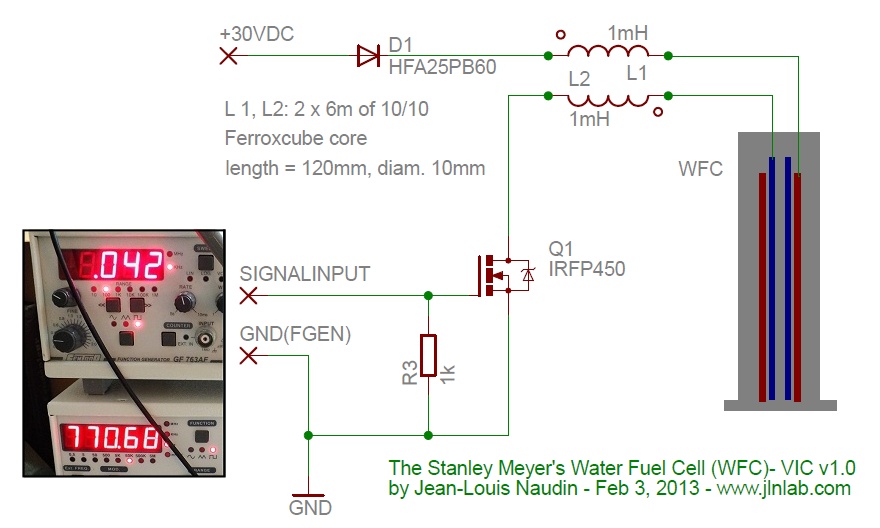
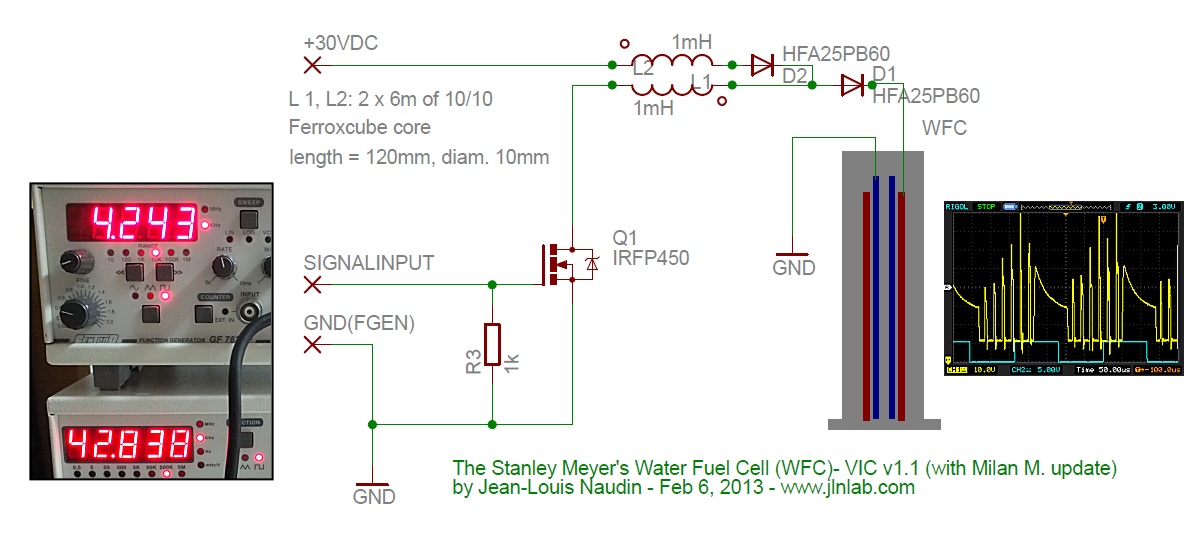
Thanks for the direction Gunther
I was curious of the meyer's circuit, built a 5 coil setup, on a big amorphous c core with 3 count - 5 inch cell in series setup. Only the core is big, the windings were mostly 32 awg, primary with 24awg like less than 100 turns.
secondary was 800 feet, -ve choke was 700 feet, +ve choke 900 feet i guess, all ugly hand wound. never paid any attention to anything.
Circuit is xmos microcontroller based circuit with pll.
I tried my best to get the edges sharp, used schotky diodes everywhere, mosfet is xys 900v i guess.
Used primary back spike heavily.
The results were strange, from the cell connected to the negative, there was brown stuff buildup between inner and outer tubes no bubbles. From the +ve side absolutely no brown stuff, tubes were clean, but tiny sized bubbles were coming as a train from the tube gap. When i left the cell running overnight, the water turns into light brown oil like stuff, with brown sediments from the -ve cell on the water bath floor. The cells were behaving like i mentioned, the +ve side tube is still clean and the bubbles were coming in slow motion because of oil like thickness of water, Also no reaction from the middle cell. i haven't seen anyone mentioning a reaction like mine.
The whole thing was happening with 12v 7-9 milli amps in the primary side coil between 3 - 5 khz. amp measurement was done using high quality analog ammeter 0 - 30 ma, also diff types of analog and digital ammeter. Almost all pointed the same reading. I even had the ma brought down to 3 ma at some point. Never measured anything in the secondary side. no voltage, no induction, no capacitance basically nothing.
If any one ask me about my preparation before entering the trial, i read/spent some time in picking up the transformer core and spent time in perfecting the pulsing circuit. no where else i spent time. the whole trial was done in less than 2 months. I spent close to 3 complete months in reading Meyer patents before that.
After this i started reading books/stuffs from Meyl, Joseph Newmann, Ed Leed, old books, army manuals etc etc
From the readings, my cell setup could have slight similarity to Meyl's explanation of 2 diff waves in the top and bottom of a coil.
I never used LTSpice before, but i have various unconventional theories now to try. i tried my best to explain meyer circuit in conventional way but failed. Even after this i have lot more to read.
Now i have the below things in hand, very very little time to spent and lots of theories to prove.
1. Oscilloscope
2. 14kv Differential probe
3. LC measuring device.
4. trying to construct a coil+ bifilar coil winder for c cores, not on bobbins, i don't want to change the core yet.
5. Altera Cyclone IV FPGA, Xmos was not good enough for the ADC. Need to try Gunther's PGen. But i am going for the whole process kind of thing, that Gunther talks about.
The painful part is, all my theories are around magnetic, electric and electromagnetic unconventional style, which is directly related to the coil winding and core setup. my efforts on FPGA will have to wait. The coil/bifilar winding on C/ toroidal core is the bottle neck.
Desperately need a coil winder, building is going very slow.
I was of the opinion that the simulation softwares won't simulate unconventional circuits realistically.
Example meyer's circuit has inductor with distributed capacitance, bifilar coil with distributed capacitance etc.
Can this simulation software predict/simulate anything like this.
If its worth time spending i will take up LTSpice next.
99% of the reading in web has no essence. That's why i want to pose my questions and expect answers to direct me into new theories, double check my concepts and even scrutinize it.
Lets see how it goes in the second attempt. A long way to go.
LTSpice hmm...


